SERVICING
29 Rev 1
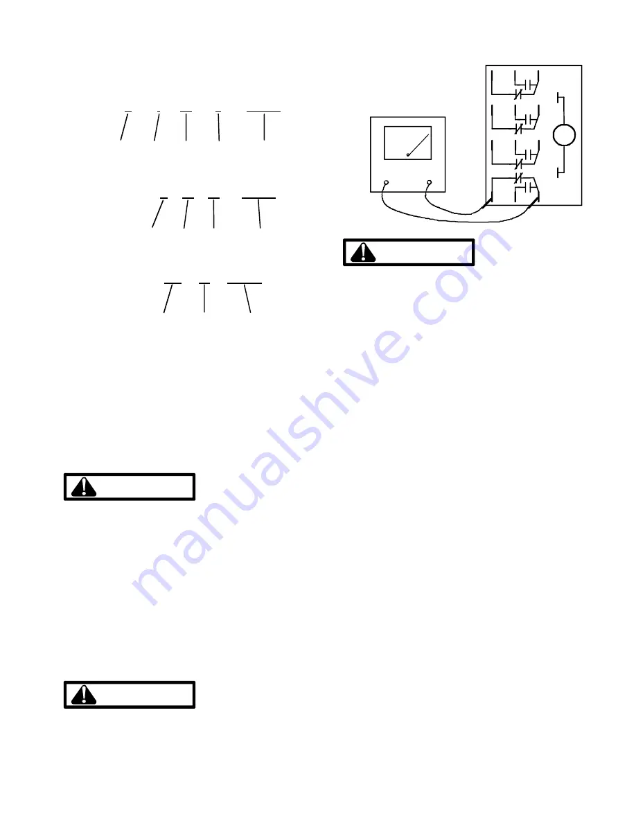
Compressor Serial Number Identification
COPELAND COMPRESSOR
E · 93 J 123456
Motor Shift Year Month Serial No
TECUMSEH COMPRESSOR
T: G 22 93C 123456
Month Day Year Serial No
Day of
Year
Year Serial No
BRISTOL COMPRESSOR
291 93 123456
S-18 TESTING CRANKCASE HEATER
The crankcase heater must be energized a minimum of four
(4) hours before the condensing unit is operated.
Crankcase heaters are used to prevent migration or accu-
mulation of refrigerant in the compressor crankcase during
the off cycles and prevents liquid slugging or oil pumping on
start up.
A crankcase heater will not prevent compressor damage
due to a floodback or over charge condition.
WARNING
Disconnect Electrical Power Supply:
1. Disconnect the heater lead in wires.
2. Using an ohmmeter, check heater continuity - should
test continuous, if not, replace.
NOTE:
The positive temperature coefficient crankcase
heater is a 40 watt 265 voltage heater. The cool resistance
of the heater will be approximately 1800 ohms. The resis-
tance will become greater as the temperature of the com-
pressor shell increases.
S-20 CHECKING DEFROST RELAY CONTACTS
With power OFF:
WARNING
Disconnect Electrical Power Supply:
1. Remove the wire leads from the defrost relay terminals.
2. Using an ohmmeter, test continuity between terminals.
Contact positions are shown in the following drawing. If
not as above, replace relay.
13
14
3
7
11
2
6
10
1
5
9
4
8
12
TESTING DEFROST RELAY
WARNING
LINE VOLTAGE NOW PRESENT.
3. Energize the relay by applying 24 volts to the relay coil.
4. With power on, retest with ohmmeter, readings should
be opposite that read in step 2, (N.O. contacts should be
closed, N.C. contacts should be open). If not as above,
replace the relay.
S-21 CHECKING REVERSING VALVE AND SOLE-
NOID
Occasionally the reversing valve may stick in the heating or
cooling position or in the mid-position.
When stuck in the mid-position, part of the discharge gas
from the compressor is directed back to the suction side,
resulting in excessively high suction pressure. An increase
in the suction line temperature through the reversing valve
can also be measured. Check operation of the valve by
starting the system and switching the operation from COOL-
ING to HEATING and back again.
If the valve fails to change its position, test the voltage at the
valve coil terminals, while the system is in the COOLING
cycle.
NOTE
: Refer to unit wiring diagram for proper voltage, 24V
for RHA & RHD models, some previous designs used a
240V solenoid coil.
If no voltage is registered at the coil terminals, check for 24V
at "O" on the low voltage terminal board.
If voltage is registered at the coil, tap the valve body lightly
while switching the system from HEATING to COOLING,
etc. If this fails to cause the valve to switch positions,
remove the coil connector cap and test the continuity of the
reversing valve solenoid coil. If the coil does not test
continuous - replace it.
If the valve is inoperative - replace it.


