


12
2. The temperature rise must be within the range specified
on the rating plate.
NOTE: Air temperature rise is the temperature difference
between supply and return air.
With a properly designed system, the proper amount of
temperature rise will normally be obtained when the unit is
operated at rated input with the recommended blower speed.
If the correct amount of temperature rise is not obtained, it
may be necessary to change the blower speed. A higher
blower speed will lower the temperature rise. A slower
blower speed will increase the temperature rise.
NOTE: Blower speed MUST be set to give the correct air
temperature rise through the unit as marked on the rating
plate.
CHECKING EXTERNAL STATIC PRESSURE
The total external static pressure must be checked on this
unit to determine if the airflow is proper.
CHANGING BLOWER SPEEDS
WARNING
To avoid death or personal injury due to
electric shock, remove electrical power from
the unit before changing speed taps on the
blower motor.
Refer to the wiring diagram on the unit to verify speed tap
settings.
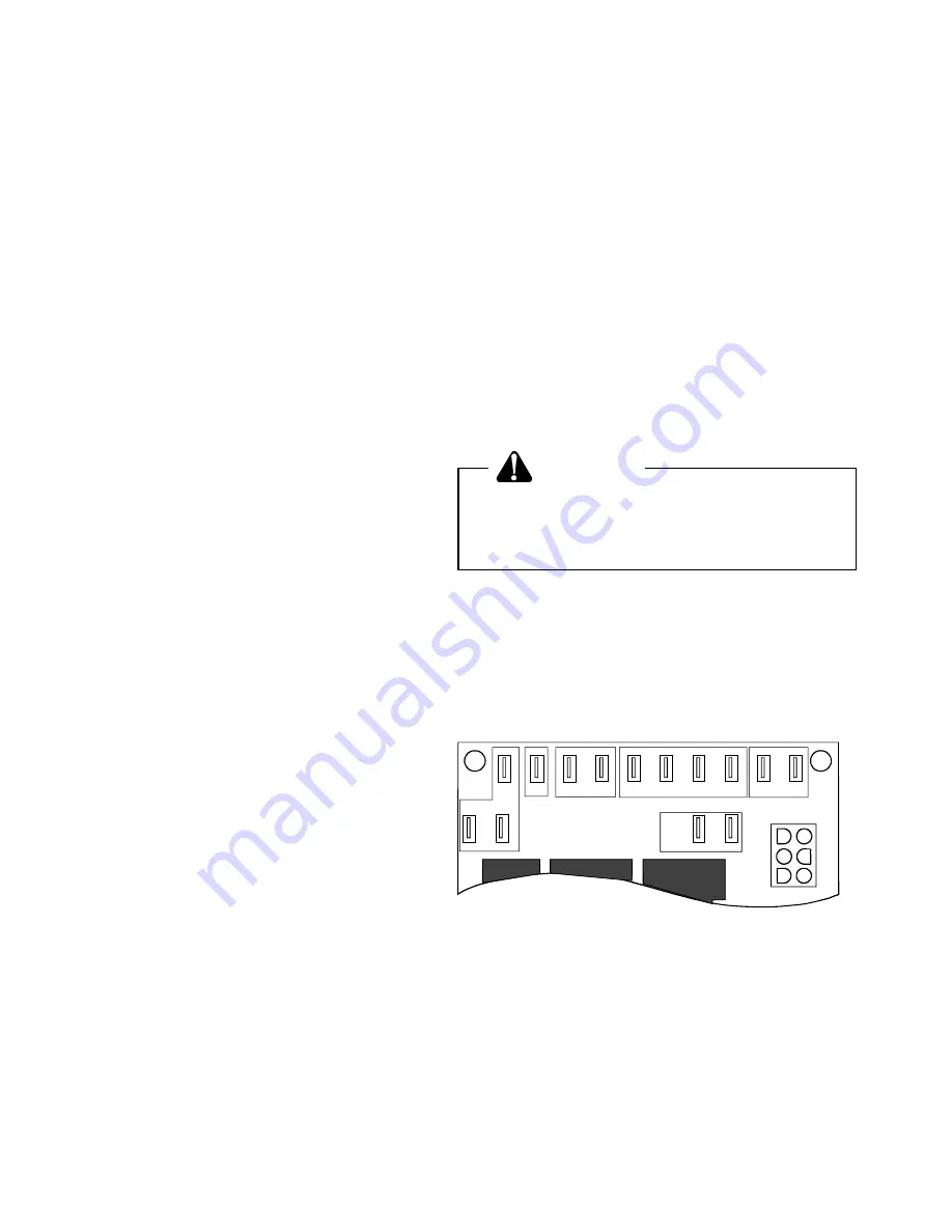
Blower speeds can be changed on the fan timer board.
Both heat speed and cool speed terminals are supplied on
the board along with two unused motor lead terminals
(Figure 15).
3
DI
UNUSED
NEUTRAL
C
X
XFMR
SEC
MOTOR
LEADS
1
2
S
S
C
OOL
HE
AT
S
CIR BLOWER
Figure 15
Control Board (Top)
CHECK LIMIT
Check limit control operation after 15 minutes of operation
by blocking the return air grille(s).
1. After several minutes the main burners must go OFF.
Blower will continue to run.
2. Remove air restrictions and main burners will relight
after a cool down period of a few minutes.
Adjust the thermostat setting below room temperature.
1. Main burners must go off.
To adjust the pressure regulator, remove the adjustment
screw or cover on the gas valve. Turn out (counterclock-
wise) to decrease pressure, turn in (clockwise) to increase
pressure. Only small variations in gas flow should be made
by means of the pressure regulator adjustment. In no case
should the final manifold pressure vary more than plus or
minus 0.3 inches water column from the specified pressure.
Any major changes in flow should be made by changing the
size of the burner orifices. The measured input rate to the
furnace must not exceed the rating specified on the unit
rating plate.
For natural gas, the manifold pressure must be between 3.0
and 3.6 inches water column (3.5 nominal).
For propane gas, the manifold pressure must be between
9.7 and 10.3 inches water column (10.0 nominal).
CHECK THE GAS INPUT (NATURAL GAS ONLY)
NOTE: On outdoor equipment, the gas input will vary with
the temperature of the gas. Rated input will be obtained at
approximately 10° F. With warmer ambient and gas tem-
peratures, the input will decrease. Example: At 70° F the
input will decrease 12%.
To measure the gas input using the gas meter proceed as
follows:
1. Turn off gas supply to all other appliances except the
unit.
2. With the unit operating, time the smallest dial on the
meter for one complete revolution. If this is a 2 cubic foot
dial, divide the seconds by 2; if it is a 1 cubic foot dial, use
the seconds as is. This gives the seconds per cubic foot
of gas being delivered to the unit.
3. INPUT=GAS HTG VALUE x 3600 / SEC. PER CUBIC
FOOT
Example: Natural gas with a heating value of 1000 BTU per
cubic foot and 34 seconds per cubic foot as determined by
Step 2, then:
Input = 1000 x 3600 / 34 = 106,000 BTU per Hour.
NOTE: BTU content of the gas should be obtained from
the gas supplier. This measured input must not be
greater than shown on the unit rating plate.
4. Relight all other appliances turned off in step 1. Be sure
all pilot burners are operating.
CHECK MAIN BURNER FLAME
Flames should be stable, soft and blue (dust may cause
orange tips but they must not be yellow) and extending
directly outward from the burner without curling, floating or
lifting off.
CHECK TEMPERATURE RISE
Check the temperature rise through the unit by placing
thermometers in supply and return air registers as close to
the unit as possible. Thermometers must not be able to
sample temperature directly from the unit heat exchangers,
or false readings could be obtained.
1. All registers must be open; all duct dampers must be in
their final (fully or partially open) position and the unit
operated for 15 minutes before taking readings.