background image

15

12

13

12

13

12

13

12

13

OFF

OFF

OFF

OFF

ON

ON

ON

ON

25%

50%*

Fan Only Selection (*indicates factory setting)

75%

100%

S12

S13

S12

S13

S12

S13

S13

OFF

OFF

OFF

OFF

ON

ON

ON

ON

Fan Only Selection (*indicates factory setting)

Figure 24

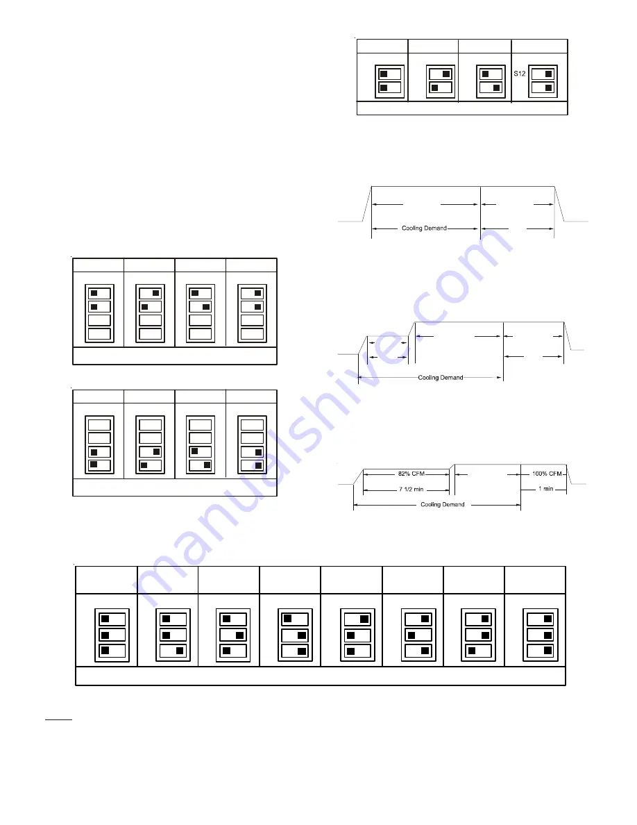
• Profile A provides only an OFF delay of one (1) minute at

100% of the cooling demand airflow.

OFF

100% CFM

100% CFM

1 min

OFF

Figure 26

• Profile B ramps up to full cooling demand airflow by first

stepping up to 50% of the full demand for 30 seconds.  The
motor then ramps to 100% of the required airflow.  A one
(1) minute OFF delay at 100% of the cooling airflow.

50% CFM

1/2 min

100% CFM

100% CFM

1 min

OFF

OFF

Figure 27

• Profile C ramps up to 82% of the full cooling demand air-

flow and operates there for approximately 7 1/2 minutes.
The motor then steps up to the full demand airflow. Profile
C also has a one (1) minute 100% OFF delay.

100% CFM

OFF

OFF

Figure 28

5. Continuous fan speeds that provide 25, 50, 75, and 100% of

the air handler’s maximum airflow capability are selectable
via dip switches S12 and S13.

If the air handler’s maximum airflow capability is 2000 CFM
and 25% continuous fan speed is selected, the continuous
fan speed will be 0.25 x 2000 CFM = 500 CFM.

6. The multi-circulator blower also offers several custom ON/

OFF ramping profiles.  These profiles may be used to enhance
cooling performance and increase comfort level.  The ramp-
ing profiles are selected using DIP switches 5 and 6.  Refer to
the following 

Dip Switches - Cooling Airflow Ramping Pro-

files

 figure for switch positions and their corresponding taps.

Refer to the bullet points below for a description of each
ramping profile.  Verify profile selection by counting the
green CFM LED blinks and timing each step of the ramping
profile.

S1

S2

S1

S2

S1

S2

S1

S2

OFF

OFF

OFF

OFF

ON

ON

ON

ON

Tap A

Tap B

Cooling Airflow Speed Tap (*indicates factory setting)

Tap C

Tap D*

Figure 22

S3

S4

OFF

OFF

OFF

OFF

ON

ON

ON

ON

+5%

-5%

Airflow Adjust Taps (*indicates factory setting)

+10%

-10%

S3

S4

S3

S4

S3

S4

Dip Switches -

Cooling Airflow and Airflow Adjust Taps

Figure 23

NOTE:

 Upon start up in communicating mode the


circuit board may display an “Ec” error. This is an indication that the dip switches

on the control board need to be configured in accordance with the Electric Heating Airflow Table.  Configuring the dip switches
and resetting power to the unit will clear the error code.

Within the thermostat user menu, CTK0* communicating thermostat will display 20 kW for OFF-OFF-ON dip switch selection and
21 kW for OFF-OFF-OFF dip switch selection.

S9

S10

OFF

OFF

OFF

OFF

ON

ON

ON

ON

21 kW* or

25 kW*

19 kW or

20 kW

Electric Heating Airflow (*indicates factory setting)

15 kW

10 kW

OFF

OFF

OFF

OFF

ON

ON

ON

ON

8 kW

6 kW

5 kW

3 kW

S11

S9

S10

S11

S9

S10

S11

S9

S10

S11

S9

S10

S11

S9

S10

S11

S9

S10

S11

S9

S10

S11

Figure 25

Summary of Contents for AVPTC25B14

Page 1: ... 2 0 Airflow Low Leakage Rate 11 14 24 Volt Wiring 11 15 Auxiliary Alarm Switch 12 16 AVPTC Motor Orientation 12 17 Circulator Blower 13 18 Heat Kit Selection 16 19 Troubleshooting 16 20 ComfortNet System 17 21 Start Up Procedure 19 23 Communications Troubleshooting Chart 20 24 Air Handler Advanced Features Menu 21 25 Troubleshooting 22 26 DiagnosticCodes 26 27 WiringDiagrams 27 ONLY PERSONNEL THA...

Page 2: ...ada electrical grounding is to be in accordance with the Canadian Electric Code CSA C22 1 uninterrupted unbroken When installing or servicing this equipment safety clothing including hand and eye protection is strongly recommended If installing in an area that has special safety requirements hard hats etc bserve these requirements o To prevent the risk of property damage personal injury or death d...

Page 3: ...54 4729 5 Pre Installation Considerations 5 1 Preparation Keep this document with the unit Carefully read all instruc tions for the installation prior to installing product Make sure each step or procedure is understood and any special considerations are taken into account before starting instal lation Assemble all tools hardware and supplies needed to complete the installation Some items may need...

Page 4: ... Condensate Kit CMK0013 Condensate Kit CMK0014 Condensate Kit AVPTC25B14 AVPTC29B14 AVPTC31C14 AVPTC49D14 AVPTC33C14 AVPTC49C14 AVPTC37B14 AVPTC37C14 AVPTC61D14 AVPTC39C14 AVPTC37D14 AVPTC59C14 AVPTC59D14 CONDENSATE KIT TABLE 1 6 3 Downflow Horizontal Right Installation IMPORTANT NOTE In the downflow application to prevent coil pan sweating a downflow kit DFK is available through your local Goodma...

Page 5: ... the specification for the condenser heat pump 7 2 Tubing Preparation All cut ends are to be round burr free and clean Failure to follow this practice increases the chances for refrigerant leaks The suction line is spun closed and requires tubing cutters to remove the closed end NOTE To prevent possible damage to the tubing joints do not handle coil assembly with manifold or flowrator tubes Always...

Page 6: ...nockout Upper Tie Plate Control Deck Downflow Bracket Center Support Filter Bracket Filter Access Panel Coil Slides on the downflow bracket IMPORTANT NOTE Ensure coil slides on the rails along the groove provided on the drain pan side walls Failure to do so will result in improper condensate drainage COIL INSTALLATION FOR DOWNFLOW Figure 8 Remove side drain pan extension for downflow application ...

Page 7: ...liquid line at the liquid line service valve and 4 6 from the compressor on the suction line Ensure the thermometer makes adequate contact and is insulated for best possible readings Use liq uid line temperatice to determine subcooling and vapor tem perature to determine superheat 3 Check subcooling and superheat Systems with TXV applica tion should have a subcooling of 7 to 9 F and superheat of 7...

Page 8: ...ines located inside the building or above a fin ished living space to prevent sweating Install a condensate trap to ensure proper drainage NOTE When units are installed above ceilings or in other locations where damage from condensate overflow may occur it is MANDATORY to install a field fabricated auxiliary drain pan under the coil cabinet enclosure The installation must include a P style trap th...

Page 9: ... 0 8 1 2 1 5 2 1 2 5 3 7 4 9 6 2 1 4 0 0 7 1 1 1 3 1 8 2 1 3 2 4 2 5 3 1 6 0 0 6 9 1 2 1 5 1 9 2 8 3 7 4 6 1 8 0 0 5 8 1 0 1 4 1 6 2 5 3 3 4 1 2 0 0 0 5 7 9 1 2 1 5 2 2 3 0 3 7 CFM HEAT KIT NOM INAL k W 230 1 60 SUPPLY VOLTAGE TEMP RISE F Table 2 3 5 6 8 1 0 1 5 1 9 2 0 2 5 8 0 0 1 1 1 8 2 2 3 0 3 5 5 4 1 0 0 0 9 1 4 1 8 2 4 2 8 4 2 1 2 0 0 7 1 2 1 5 2 0 2 4 3 5 4 7 5 9 1 4 0 0 6 1 0 1 3 1 7 2 0 3...

Page 10: ...for wire sizing The unit MCA for the air handler and the optional electric heat kit can be found on the unit Series and Rating Plate Wire must be sized to allow no more than a 2 voltage drop from the building breaker fuse panel to the unit Wires with different insulation temperature rating have varying ampacities be sure to check the temperature rat ing used Refer to the latest edition of the Nati...

Page 11: ...g Non Communicating Thermostat Connections NOTE Wire routing must not interfere with the circulator blower operation or routine maintenance The air handler s integrated control module provides terminals for Y1 and Y2 and W1 and W2 thermostat connections This allows the air handler to support the systems shown in the following table Refer to the following figures for typical connec tions to the int...

Page 12: ...Orientation Figure 20 1 2 R C Air Handler Integrated Control Module Typical Two Stage Cool Two Stage Heat Heat Pump Thermostat Dehumidistat Optional G W1 W2 Y1 Y2 O DEHUM Remote Condensing Unit Two Stage HP NEU HOT W E R C G W2 Y1 Y2 O R C W1 Y1 Y2 O Typical Two Stage Heat Pump Heating and Auxiliary Emergency Heating Figure 17 14 2 24 Volt Dehumidistat Wiring Non Communicating Thermostat Connectio...

Page 13: ... must be checked for required airflow Any electronic air cleaners or other devices may require a specific airflow consult installation instructions of those devices for requirements 3 Knowing the air handler model locate the high stage cool ing airflow charts in the Specification Sheet applicable to your model Look up the cooling airflow determined in step 2 and find the required cooling speed and...

Page 14: ...o the electric heat only in either legacy mode or communicating mode operation Within thermostat user menu CTK0 communicating thermostat will display 20KW for OFF OFF ON dip switch selection 21kW for OFF OFF OFF dip swith selection NR Not rated For match up with a 3 ton outdoor unit Airflow for 5kW up to 15kW heater kits shall be set to 1300 cfm speed tap of ON OFF ON For match up with a 3 5 ton o...

Page 15: ...be used to enhance cooling performance and increase comfort level The ramp ing profiles are selected using DIP switches 5 and 6 Refer to the following Dip Switches Cooling Airflow Ramping Pro files figure for switch positions and their corresponding taps Refer to the bullet points below for a description of each ramping profile Verify profile selection by counting the green CFM LED blinks and timi...

Page 16: ...R available for a given air handler 18 Heat Kit Selection For heat kit selection see the Specification Sheet for each specific Air Handler 19 Troubleshooting 19 1 Electrostatic Discharge ESD Precautions NOTE Discharge body s static electricity before touching unit An electrostatic discharge can adversely affect electrical components Use the following precautions during air handler installation and...

Page 17: ...features of the ComfortNet system Two way digital communications is accomplished using only two wires The thermostat and subsystem controls are powered with 24 VAC Thus a maximum of 4 wires between the equipment and thermostat is all that is required to operate the system 20 1 AirflowConsideration Airflow demands are managed differently in a fully communicat ing system than they are in a non commu...

Page 18: ...t six faults detected by the air handler Faults are stored most recent to least recent Any consecutively re peated fault is stored a maximum of three times Example A clogged return air filter causes the air handler s motor to repeat edly entera limiting condition The control will only store this fault the first three consecutive times the fault occurs NOTE It is highly recommended that the fault h...

Page 19: ...rom any areas where there may be objectionable odors flammable vapors or products of combustion such as carbon monoxide CO which may cause serious personal injury or death 22 Regular Maintenance HIGH VOLTAGE Failure to do so may cause property damage personal injury or death Disconnect ALL power before servicing Multiple power sources may be present The only item to be maintained on a regular basi...

Page 20: ...nstalled as a legacy traditional system Check communications wiring data 1 data 2 wires Check wire connections at terminal block Verify air handler installation type legacy traditional or communicating Check data 1 data 2 voltages Turn power OFF prior to repair Verify wires at terminal blocks are securely twisted together prior to inserting into terminal block Verify data1 and data voltages as des...

Page 21: ...YES Selecting YES clears the fault history NOTE Consecutively repeated faults are shown a maximum of 3 times Submenu Item Model Number MOD NUM Displays the modular blower model number Serial Number SER NUM Displays the modular blower serial number Optional Software SOFTWARE Displays the application software revision Submenu Item User Modifiable Options Comments Heat Airflow Trim HT TRM 10 to 10 in...

Page 22: ...ied in shared data set HTR TOO SMALL EC x Heater kit selected via dipswitches is too small for heater kits in shared data set x Verify electric heat dipswitch settings x Verify the installed electric heater is valid for the air handler blower Check nameplate or Specification Sheet applicable to your model for allowable heater kit s x Verify shared data set is correct for the specific model Re popu...

Page 23: ...age d0 x Data not yet on network NO NET DATA d0 x Air handler blower does not contain any shared data x Populate shared data set using memory card x Turn power OFF prior to repair x Use memory card for the specific model x Insert memory card BEFORE turning power ON Memory card may be removed after data is loaded x Error code will be cleared once data is loaded x Turn power off before removing memo...

Page 24: ...motor horse power MOTOR MISMATCH b2 x Incorrect circulator blower motor in air handler blower x Incorrect shared data set in integrated control module x Verify circulator blower motor horse power is the same specified for the specific air handler blower model Replace is necessary x Verify shared data set is correct for the specific model Re populate data using correct memory card if required x Tur...

Page 25: ...atures x Check power to air handler blower Verify line voltage to blower is within the range specified on the air handler blower rating plate x See Installation Instructions for installation requirements x Turn power OFF prior to repair x Air handler blower fails to operate x Integrated control module LED display provides indicated error code x ComfortNet thermostat Call for Service icon illuminat...

Page 26: ...IP OR LOST ROTOR b5 BLOWER MOTOR ROTOR LOCKED b6 OVER UNDER VOLTAGE TRIP OR OVER TEMPERATURE TRIP b7 INCOMPLETE PARAMETER SENT TO MOTOR b9 LOW INDOOR AIRFLOW C1 LOW STAGE COOL LEGACY MODE ONLY C2 HIGH STAGE COOL LEGACY MODE ONLY P1 LOW STAGE HEAT PUMP HEAT LEGACY MODE ONLY P2 HIGH STAGE HEAT PUMP HEAT LEGACY MODE ONLY h1 EMERGENCY HEAT LOW COMMUNICATING MODE ONLY h2 EMERGENCY HEAT HIGH COMMUNICATI...

Page 27: ...ICE INTEGRATED CONTROL LOW VOLTAGE 24V FIELD SPLICE INTERNAL TO FIELD GRND OVERCURRENT BK BLACK OR ORANGE BL BLUE PK PINK GY GRAY RD RED WH WHITE PU PURPLE YL YELLOW BR BROWN COLOR CODES GN GREEN NOTES 1 PLACE RED WIRES ON TRANSFORMER TERMINAL 2 FOR 208 VAC OPERATION 2 MANUFACTURER S SPECIFIED REPLACEMENT PARTS MUST BE USED WHEN SERVICING 3 IF ANY OF THE ORIGINAL WIRES AS SUPPLIED WITH THIS UNIT M...

Page 28: ...ing diagram on the unit for the most up to date wiring HIGH VOLTAGE DISCONNECT ALL POWER BEFORE SERVICING MULTIPLE POWER SOURCES MAY BE PRESENT FAILURE TO DO SO MAY CAUSE PROPERTY DAMAGE PERSONAL INJURY OR DEATH WARNING 3 Phase Heat Kit 27 Wiring Diagrams ...

Page 29: ...ly maintained filter will keep the indoor coil of your comfort system clean A dirty coil could cause poor operation and or severe equipment damage Your air filter or filters could be located in your furnace in a blower unit or in filter grilles in your ceiling or walls The installer of your air conditioner or heat pump can tell you where your filter s are and how to clean or replace them Check you...

Page 30: ...30 THIS PAGE WAS LEFT BLANK INTENTIONALLY ...

Page 31: ...31 THIS PAGE WAS LEFT BLANK INTENTIONALLY ...

Page 32: ...and you purchased to be directed to the feedback page PRODUCTREGISTRATION Thank you for your recent purchase Though not required to get the protection of the standard warranty registering your product is a relatively short process and entitles you to additional warranty protection except that failure by California and Quebec residents to register their product does not diminish their warranty righ...

Reviews: