SERVICING
36
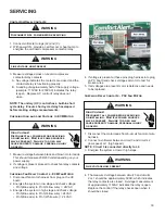
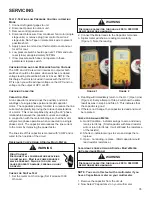
3. Now connect the capacitor terminals to the multi-meter
leads.
4. If the reading is near to the actual value of the capacitor
(i.e. the printed value on the capacitor). The capacitor is
good. (Note that the reading may be less than the actual
printed value of the capacitor).
5.
If you read a significantly lower capacitance or none at
all, then capacitor is dead and must be replaced.
Capacitor, Start
Scroll Compressor Models
In most cases hard start components are not required
on Scroll compressor equipped units due to a non-
replaceable check valve located in the discharge line of
the compressor. However, in installations that encounter
low lock rotor voltage, a hard start kit can improve starting
characteristics and reduce light dimming within the
home. Only hard start kits approved by Amana® brand
or Copeland should be used. “Kick Start” and/or “Super
Boost” kits are not approved start assist devices.
The discharge check valve closes off high side pressure
to the compressor after shut down allowing equalization
through the scroll flanks. Equalization requires only about
1/2 second.
To prevent the compressor from short cycling, a Time
Delay Relay (Cycle Protector) has been added to the low
voltabe circuit.
Testing a Run Capacitor Under Load
1. Measure the amperage of the wire from Herm on the
capacitor to start terminal on compressor.
2. Multiply the amperage reading by the constant of 2,652
3. Measure voltage across the capacitor between “HERM”
and “C” terminals this is the measured voltage across
the start and run terminals on the compressor.
4. Divide total from step 2 by the voltage measurement.
This total is the capacitance. This give a more accurate
measurement of the capacitor’s performance.
5. Read the rated MFD on the capacitor and compare to
your actual readings. If outside of +/- tolerance stated
on the capacitor, replacement of the capacitor may be
recommended.
Formula: Start Winding Amps x 2,652 ÷ capacitor
voltage = microfarads.
Checking Emerson UltraTech™ ECM Motors
Description
The ComfortBridge Air Handlers models utilize an
Emerson, 4-wire variable speed ECM blower motor. The
ECM blower motor provides constant CFM.
The motor is a serially communicating variable speed
motor. Only four wires are required to control the motor:
+Vdc, Common, Receive, and Transmit.
The +Vdc and Common wires provide power to the motor’s
low voltage control circuits.
General Checks/Considerations
1. Check power supply to the air handler or modular
blower. Ensure power supply is within the range
specified on rating plate.
2. Check motor power harness. Ensure wires are
continuous and make good contact when seated in the
connectors. Repair or replace as needed.
3. Check motor control harness. Ensure wires are
continuous and make good contact when seated in the
connectors. Repair or replace as needed.
4. Check thermostat and thermostat wiring. Ensure
thermostat is providing proper cooling/heating/
continuous fan demands. Repair or replace as needed.
5.
Check blower wheel. Confirm wheel is properly seated
on motor shaft. Set screw must be on shaft flat and
torqued to 165 in-lbs minimum. Confirm wheel has no
broken or loose blades. Repair or replace as needed.
6. Ensure motor and wheel turn freely. Check for
interference between wheel and housing or wheel and
motor. Repair or replace as needed.
7. Check housing for cracks and/or corrosion. Repair or
replace as needed.
8. Check motor mounting bracket. Ensure mounting
bracket is tightly secured to the housing. Ensure
bracket is not cracked or broken.
Emerson UltraCheck-EZ™ Diagnostic Tool
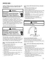
The Emerson UltraCheck-EZTM diaganostic tool may be
used to diagnose the ECM motor.
WARNING
High Voltage!
Disconnect all power before servicing
or installing. Multiple power sources
may be present. Failure to do so may
cause property damage, personal injury
or death.
To use the diagnostic tool, perform the following steps:
1. Disconnect power to the air handler.
2. Disconnect the 4-circuit control harness from the motor.
3. Plug the 4-circuit connector from the diagnostic tool into
the motor control connector.
4. Connect one alligator clip from the diagnostic tool to a
ground source.
5. Connect the other alligator clip to a 24VAC source.
NOTE: The alligator clips are NOT polarized.
Summary of Contents for ASXC16
Page 4: ...PRODUCT IDENTIFICATION 4 ...
Page 5: ...PRODUCT IDENTIFICATION 5 ...


