background image

2

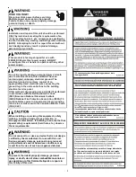
HIGH VOLTAGE!


Failure to do so may cause property damage,
personal injury or death.

Disconnect ALL power before servicing.
Multiple power sources may be present.

Installation and repair of this unit should be performed

by individuals meeting the requirements of an

“entry level technician”

 as specified by 

the Air-Conditioning, Heating and Refrigeration Institute
(AHRI).  Attempting to install or repair this unit without
such background may result in product damage, 
personal injury or death.

ONLY 

, at a  minimum,

This product is factory-shipped for use with 
208/240/1/60 electrical power supply. 
reconfigure this air handler to operate with any other 
power supply.

DO NOT 

To avoid property damage, personal injury or death 
due to electrical shock, this unit MUST have an 

 electrical ground. The 

electrical ground circuit may consist of an 
appropriately sized electrical wire connecting the 
ground lug in the unit control box to the building 
electrical service panel.
Other methods of grounding are permitted if performed 
in accordance with the National Electric Code 
(NEC)/American National Standards Institute 
(ANSI)/National Fire Protection Association (NFPA) 70 
and local/state codes. In Canada, electrical grounding 
is to be in accordance with the Canadian Electric Code  
(CSA) C22.1.

uninterrupted, unbroken

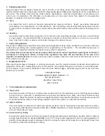
When installing or servicing this equipment, safety 
clothing, including hand and eye protection, is 
strongly recommended.  If installing in an area that has 
special safety requirements (hard hats, etc.),  bserve 
these requirements.

o

Do not connect to or use any device that is not design-
certified by the manufacturer for use with this unit. 
Serious property damage, personal injury, reduced 
unit performance and/or hazardous conditions may 
result from the use of such non-approved devices.

To prevent the risk of property damage, personal 
injury, or death, do not store combustible materials or 
use gasoline or other flammable liquids or vapors in 
the vicinity of this unit.

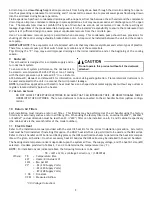
CO can cause serious illness including permanent brain
damage or death.

Advertencia especial para la instalación de calentadores ó manejadoras 

de aire en áreas cerradas como estacionamientos ó cuartos de servicio.

El monóxido de carbono puede causar enfermedades severas 
como  daño cerebral permanente ó muerte.

Las emisiones de monóxido de carbono pueden circular a través
del aparato cuando se opera en cualquier modo. 

RISQUE D'EMPOISONNEMENT AU MONOXYDE DE CARBONE

Cette ventilation est nécessaire pour éviter le danger d'intoxication
au CO pouvant survenir si un appareil produisant du monoxyde 
de carbone continue de fonctionner au sein de la zone confinée.

Summary of Contents for ARUF**14 Series

Page 1: ...s Regulations 3 4 Replacement Parts 3 5 Pre Installation Considerations 3 5 1 Preparation 3 5 2 System Matches 3 5 3 Interconnecting Tubing 3 5 4 Clearances 4 5 5 Horizontal Applications 4 6 Installation Location 4 6 1 Upflow Installation 4 6 2 Horizontal Left Installation 4 6 3 Downflow 4 6 4 Horizontal Right Installation 5 7 Refrigerant Lines 7 7 1 Tubing Size 7 7 2 Tubing Preparation 7 7 3 Spec...

Page 2: ...to be in accordance with the Canadian Electric Code CSA C22 1 uninterrupted unbroken When installing or servicing this equipment safety clothing including hand and eye protection is strongly recommended If installing in an area that has special safety requirements hard hats etc bserve these requirements o Do not connect to or use any device that is not design certified by the manufacturer for use ...

Page 3: ...ailure to follow these regulations may harm the environment and can lead to the imposition of substantial fines Should you have any questions please contact the local office of the EPA and or refer to EPA s website www epa gov 4 Replacement Parts When reporting shortages or damages or ordering repair parts give the complete product model and serial numbers as stamped on the product Replacement par...

Page 4: ...moval Refer to Figure 1 remove the two 2 screws that secure the drip shield support brackets to the condensate collectors front and back Unsnap the side drain pan from vertical bottom drain pan using a screw driver or any small lever The side drain pan and drip shield brackets may now be removed The bottom left drain connection is the primary drain for this application and condensate drain line mu...

Page 5: ...red on units with 21 wide cabinet Remove and retain the two 2 screws that secure the center support to the cabi net Remove the center support 4 Using the drain pan to hold the coil assembly slide the coil assembly back into the cabinet on the downflow brackets as shown in Figure 8 5 Re install the center support if removed using the two 2 screws removed in Step 4 6 Re install the access panels rem...

Page 6: ...NOLOGY Figure 7 INTERNAL PART TERMINOLOGY Figure 6 ACCESS PANEL CONFIGURATION FOR DOWNFLOW OR HORIZONTAL RIGHT Figure 9 Coil Slides on the downflow bracket IMPORTANT NOTE Ensure coil slides on the rails along the groove provided on the drain pan side walls Failure to do so will result in improper condensate drainage COIL INSTALLATION FOR DOWNFLOW Figure 8 ...

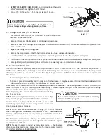
Page 7: ...when brazing to avoid burning the serial plate or the finish of the unit Heat trap or wet rags must be used to protect heat sensitive components such as service valves and TXV valves sensing bulb 7 4 Tubing Connections for Flowrator Model 1 Loosen the 13 16 nut 1 TURN ONLY to allow high pressure tracer gas to escape No gas indicates a possible leak 2 After the gas has been expelled remove the nut ...

Page 8: ...1 2 3 5 turns should be expected at this torque 1 Ensure drain pan hole is not obstructed 2 To prevent potential sweating and dripping on to finished space it may be necessary to insulate the condensate drain line located inside the building Use Armaflex or similar material A secondary condensate drain connection has been provided for areas where the building codes require it Pitch all drain lines...

Page 9: ...nformation on duct sizing and application Flame retardant ductwork is to be used and sealed to the unit in a manner that will prevent leakage NOTE A downflow application with electric heat must have an L shaped sheet metal supply duct without any outlets or registers located directly below the heater 9 1 Return Ductwork DO NOT LOCATE THE RETURN DUCTWORK IN AN AREA THAT CAN INTRODUCE TOXIC OR OBJEC...

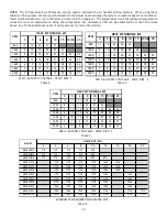
Page 10: ...e 3 3 5 6 8 10 15 19 20 25 800 11 18 22 30 35 1000 9 14 18 24 28 42 1200 7 12 15 20 24 35 47 59 1400 6 10 13 17 20 30 40 51 1600 6 9 11 15 18 27 35 44 1800 5 8 10 13 16 24 31 39 2000 4 7 9 12 14 21 28 35 CFM HEAT KIT NOMINAL kW 208 1 60 SUPPLY VOLTAGE TEMP RISE F Table 4 3 5 6 8 10 15 19 20 25 800 10 17 21 28 33 1000 8 13 17 22 27 40 1200 7 11 14 19 22 33 45 56 1400 6 10 12 16 19 29 38 48 1600 5 8...

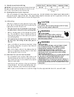
Page 11: ...rmining the correct wire size 12 3 Maximum Overcurrent Protection MOP Every installation must include an NEC USA or CEC Canada approved overcurrent protection device Also check with local or state codes for any special regional requirements Protection can be in the form of fusing or HACR style circuit breakers The Series and Rating Plate pro vides the maximum overcurrent device permissible NOTE Fu...

Page 12: ...age or multi stage whether the outdoor section is an air conditioner or heat pump and whether the outdoor section is single stage or two stage The 24V control voltage connects the air handler to the room thermostat and condenser Low voltage wiring must be copper conductors A minimum of 18AWG must be used for installations up to 100 feet Low voltage wiring must be connected through the top of the c...

Page 13: ...ne must be trapped and pitched to allow for drainage Low voltage wiring is properly connected Auxiliary drain is installed when necessary and pitched to allow for drainage Unit is protected from vehicular or other physical damage Return air is not obtained from nor are there any return air duct joints that are unsealed in areas where there may be objectionable odors flammable vapors or products of...

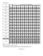
Page 14: ...1540 1470 1390 1300 1190 1060 HIGH 1900 1830 1740 1645 1540 1420 1280 LOW 1420 1370 1310 1240 1125 1045 960 MED 1625 1585 1515 1435 1350 1235 1095 HIGH 1930 1890 1820 1735 1635 1505 1355 LOW 1410 1360 1290 1210 1120 1010 920 MED 1610 1540 1470 1390 1300 1190 1060 HIGH 1900 1830 1740 1645 1540 1420 1280 LOW 1530 1500 1460 1405 1350 1280 1155 MED 1950 1885 1830 1785 1745 1670 1595 HIGH 2235 2170 210...

Page 15: ...R TO CONNECT Y FROM THE THERMOSTAT TO THE Y2 ON THE LOW VOLTAGE TERMINAL BOARD An equivalent thermostat can be used in place of the manufacturer s thermostat part number NOTE Some models feature low voltage wires and do not include a terminal block For those applications use the corresponding colored wires NOTES 1 OUTDOOR THERMOSTAT OT 1 SHOULD BE THE FIRST TO CLOSE AND THE LAST TO OPEN 2 JUMPER W...

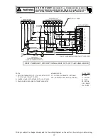
Page 16: ... WHEN USING OUTDOOR THERMOSTAT NOMENCLATURE OT OUTDOOR THERMOSTAT OPTIONAL EHR EMERGENCY HEAT RELAY OPTIONAL COLOR CODES RD RED YL YELLOW BL BLUE BR BROWN OR ORANGE WH WHITE Y G W W2 R COOLING UNIT WITH OPTIONAL HEAT KITS OF 15 kW AND ABOVE AND ROOM THERMOSTAT WITH TWO STAGES OF HEAT C W1 W2 Y2 Y1 O G R TB YL BL CONDENSING UNIT 24V CONNECTION BL YL GR RD 18 GA 5 WIRES WITH COOLING 4 WIRES WITHOUT ...

Page 17: ...STAT OT 1 SHOULD BE THE FIRST TO CLOSE AND THE LAST TO OPEN 2 JUMPER W1 AND W2 TOGETHER IF OT 2 IS NOT USED 3 REMOVE WIRE WHEN USING OUTDOOR THERMOSTAT NOMENCLATURE OT OUTDOOR THERMOSTAT OPTIONAL EHR EMERGENCY HEAT RELAY OPTIONAL COLOR CODES RD RED YL YELLOW BL BLUE BR BROWN OR ORANGE WH WHITE G C R HEAT PUMP UNIT WITH OPTIONAL HEAT KITS OF 15 kW AND ABOVE C W1 W2 Y2 Y1 O G R TB 18 GA 7 WIRE O Y C...

Page 18: ...EATKIT MOTOR The Electronic Blower Time Delay Relay provides power to the blower motor with a delay of 7 seconds after 24VAC is applied to G After 24VAC is removed from G the blower motor output is de energized after a delay of 65 seconds Normal Time Delays 60Hz 50Hz Turn On Delay 7 0 SEC 1 8 4 SEC 1 Turn Off Delay 65 0 SEC 1 78 0 SEC 1 Field test mode Shorting the speedup quick connect to C decre...

Page 19: ...19 THIS PAGE LEFT INTENTIONALLY BLANK ...

Page 20: ... TR WH 6 BR 5 PLF 4 4 24V 5 SEE NOTE 1 1 2 3 RC HI EM GR WIRING CODE BL EBTDR LO COM NC M1 EBTDR NO 208 240 VOLTS 1 1 PLF PLM L1 PLM 2 L2 M2 PU RC M1 BK BL MEDIUM 3 SPEED BR HIGH EM COM RD LOW IF REPLACEMENT OF THE ORIGINAL WIRES SUPPLIED WITH THIS ASSEMBLY IS NECESSARY USE WIRE THAT CONFORMS TO THE NATIONAL ELECTRIC CODE M2 PU TR 1 M2 R G C EBTDR SEE NOTE 1 FL FUSE LINK TL THERMAL LIMIT SEE NOTE ...

Page 21: ... WIRING TO BE N E C CLASS 2 WIRES RELAY EVAPORATOR MOTOR TERMINAL BOARD R EM TB BK RD BL YL BLUE BLACK RED YELLOW COMPONENT CODE BROWN PURPLE GREEN PU BR GR FEMALE PLUG CONNECTOR MALE PLUG CONNECTOR TRANSFORMER HIGH VOLTAGE LOW VOLTAGE HIGH VOLTAGE LOW VOLTAGE PLF 2 COLOR CODE TR 6 5 PLM 4 4 24V 5 1 2 3 EM WIRING CODE 208 240 VOLTS 1 1 PLF PLM L1 PLM 2 L2 IF REPLACEMENT OF THE ORIGINAL WIRES SUPPL...

Page 22: ...to the wiring diagram on the unit for the most up to date wiring HIGH VOLTAGE DISCONNECT ALL POWER BEFORE SERVICING MULTIPLE POWER SOURCES MAY BE PRESENT FAILURE TO DO SO MAY CAUSE PROPERTY DAMAGE PERSONAL INJURY OR DEATH WARNING 3 Phase Heat Kit ...

Page 23: ...or unit of your comfort system Do not construct a fence near the unit or build a deck or patio over the unit without first discussing your plans with your dealer or other quali fied servicer Restricted airflow could lead to poor operation and or se vere equipment damage Likewise it is important to keep the outdoor coil clean Dirt leaves or debris could also restrict the airflow If cleaning of the ...

Page 24: ...odman Manufacturing Company L P Visit our website at www daikincomfort com www goodmanmfg com or www amana hac com for information on Products Warranties Customer Services Parts Contractor Program and Training Financing Options is a registered trademark of Maytag Corporation or its related companies and is used under license All rights reserved ...

Reviews: