


13
13 Achieving 1.4% Low Leakage Rate
Ensure all the gaskets remain intact on all surfaces as shipped with the unit. These surfaces are areas between the upper
tie plate and blower access panel, blower access and coil access panels, and between the coil access and filter access
panels. Ensure upon installation, that the plastic breaker cover is sitting flush on the blower access panel and all access
panels are flush with each other and the cabinet. With these requirements satisfied, the unit achieves less than 1.4%
airflow leakage when tested in accordance with ASHRAE Standard 193.
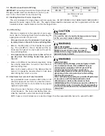
14 Start-Up Procedure
•
Prior to start-up, ensure that all electrical wires are properly sized and all connections are properly tightened.
•
All panels must be in place and secured. For Air Tight application, gasket must be positioned at prescribed loca-
tions to achieve 1.4% leakage.
•
Tubing must be leak free.
•
Condensate line must be trapped and pitched to allow for drainage.
•
Low voltage wiring is properly connected.
•
Auxiliary drain is installed when necessary and pitched to allow for drainage.
•
Unit is protected from vehicular or other physical damage.
•
Return air is not obtained from, nor are there any return air duct joints that are unsealed in, areas where there may
be objectionable odors, flammable vapors or products of combustion such as carbon monoxide (CO), which may
cause serious personal injury or death.
15 Regular Maintenance
The only item required to be maintained on a regular basis
by the user is the circulating air filter(s). Filter should be
cleaned or replaced regularly, typically once per month. A
certified service technician must perform all other services.
IMPORTANT NOTE:
If thumb screws are used to access the
filter, ensure the washer installed on the screw behind the
access panel remains in place after re-installation.
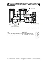
HIGH VOLTAGE!
Disconnect ALL power before servicing or
installing this unit. Multiple power sources may
be present. Failure to do so may cause property
damage, personal injury or death.


