
Troubleshooting
October 2000
RT1300056 Rev.1
9
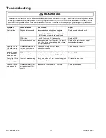
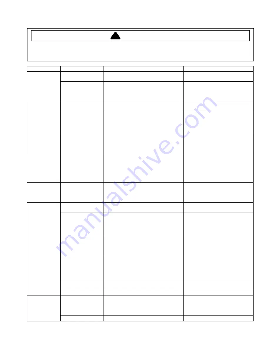
Symptom
Possible Cause
Test Procedure
Repair
Incorrect harness
wiring.
Verify correct wiring of 10-pin connector.
Correct wiring and retest.
No auger motor.
Cavity light
comes on when
water is actuated
but not when ice
is actuated.
Harness: Open
black/red wire between
connector and auger
switch.
Test black/red wire for continuity.
Repair wire or replace door.
Operational error: Lock
mode may be enabled.
Press and hold
DISPENSER LOCK
button for 4
seconds
Customer education.
Harness: Open red wire
in harness (Pin 4 on 10-
pin connector) between
connector and auger
switch.
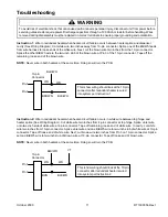
Disconnect power. Unplug 10-pin connector
from PCB and attach ohmmeter probe to
harness Pin 4 (red wire). Remove red wire from
auger switch. Attach second ohmmeter probe
to red wire. Look for less than 1
Ω
resistance.
Repair wire or terminal.
LED’s operate but
no ice or water.
Cavity light does
not come on
when ice or water
is actuated. Night
light works
properly.
PCB: Lock relay stuck
open.
Disconnect power. Remove 10-pin connector
from PCB. On PCB, measure resistance
between Pin 10 and Pin 4. Meter should read
less than 2
Ω
.
Replace PCB.
LED’s operate.
Cavity light
comes on when
ice or water
actuated, but no
auger motor.
Auger motor: Open
winding or connection.
Perform standard auger motor test.
Replace auger motor.
No night light.
Cavity light works
properly.
PCB defective.
Verify LED above
AUTO LIGHT
button is lit.
Completely cover sensor lens with coin. If
night-light turns on, then product is operating
within spec. Otherwise, PCB needs replaced.
Replace PCB.
Bulb burnt out.
Measure resistance across bulb filament. If
higher than 1k
Ω
, replace bulb.
Replace bulb.
Harness: Open white
wire between cavity light
and splice in door. Wire
not connected at light
socket.
Inspect wire for proper connection at 10-pin
connector and cavity-light socket. Ohmmeter
should show short between white wire at cavity
light and neutral on the power cord.
Repair or replace white wire or
connection, or splice in violet wire (spare)
per Instruction 1 (see Page 8), if white
wire is not accessible.
Harness: Open white
wire between 10-pin
connector and cavity
light.
Test white wire for continuity.
Repair or replace white wire or terminal.
Harness: Yellow wire
open or not connected
between 10-pin
connector and light
socket.
Test yellow wire for continuity.
Repair or replace yellow wire or attach
wire to light socket.
Incorrect harness
wiring.
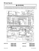
Check color-coding of wires against wiring
diagram.
Correct wiring and retest.
No light at all.
Everything else
works properly.
PCB failure.
If LED’s turn on, PCB is defective.
Replace PCB.
Switch failure: shorted
auger switch.
Remove both leads from switch. Measure
resistance across switch terminals. Resistance
is greater than 1M
Ω
in open position and less
than 1
Ω
when switch is closed.
Replace auger switch.
Ice all the time.
PCB failure.
If LED’s turn on, PCB is defective.
Replace PCB.
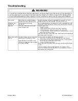
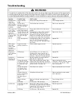
!
WARNING
To avoid risk of electrical shock that can cause death or severe personal injury, disconnect unit from power before
servicing unless tests require power. Discharge capacitors through a 10,000-ohm resistor before handling. Wires
removed during disassembly must be replaced on correct terminals to ensure proper grounding and polarization.