
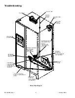
Troubleshooting
RT1300056 Rev.1
October 2000
8
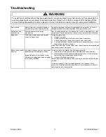
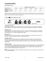
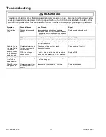
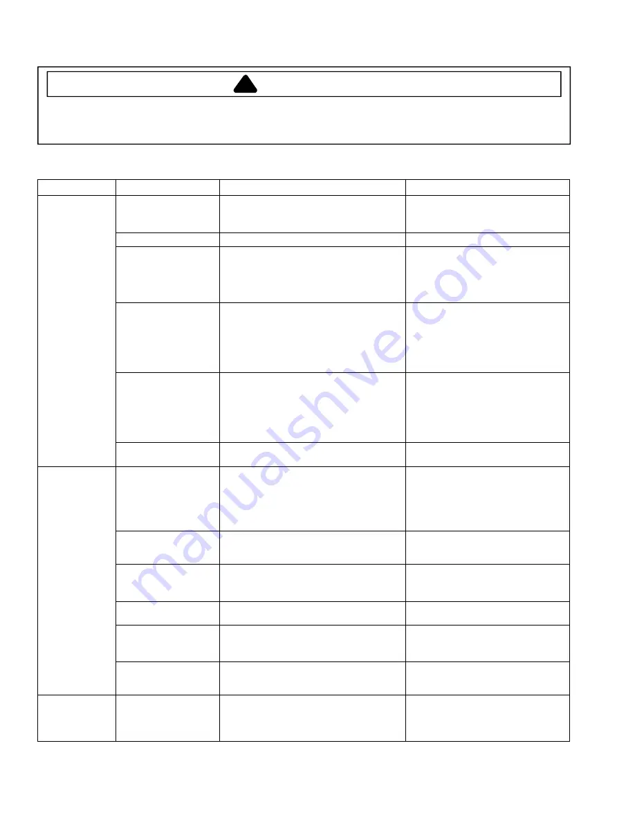
Electronic Dispenser Troubleshooting Guide
Symptom
Possible Cause
Test Procedure
Repair
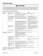
Switch failure in freezer
door.
With refrigerator powered, open freezer door.
Press freezer door switch in. If freezer light
does not turn off, switch is defective.
Replace switch and retest.
Incorrect harness wiring.
Verify wire colors on 10-pin connector.
Correct wiring and retest.
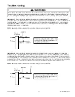
Harness: Open heater,
open white wire between
splice and heater, or
open brown wire.
Disconnect power. Remove 10-pin connector
and measure resistance between white and
brown wires. Reading should be 1.4k
Ω
±
105
Ω
.
Repair connector or wire if possible. If
not, connect redundant heater. See
Instruction 1on Page 10 for wiring
diagram. Replace door if both heaters
have failed.
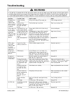
Open black wire.
Disconnect power. Unplug 10-pin connector
from PCB and attach ohmmeter probe to
harness Pin 10 (black wire). Remove top hinge
cover. Disconnect 4-pin plug. Attach second
meter probe to harness Pin 2 (black wire).
Meter should read less than 1
Ω
.
Repair black wire if possible. If not, cut
black wire at top hinge plug and at 10-pin
connector. Splice violet wire (spare) in
door harness between black wire at top
hinge plug and black wire at 10-pin
connector.
Open white wire
between top hinge and
cavity.
Disconnect power. Unplug 10-pin connector
from PCB and attach ohmmeter probe to
harness Pin 1 (white wire). Remove top hinge
cover. Disconnect 4-pin plug. Attach second
meter probe to harness Pin 1 (white wire).
Meter should read less than 1
Ω
.
Repair white wire if possible. If not, use
violet wire (spare) to connect redundant
heater. See Instruction 2 on Page 10 for
wiring diagram. Replace door if both
heaters have failed.
No LED’s lit.
PCB: Power supply.
If no LED’s turn on and wiring checks OK, PCB
is defective.
Replace PCB.
Failed water actuator
switch.
Remove both leads from switch and measure
resistance across switch terminals. Press
finger against actuator to close switch.
Resistance should read less than 1
Ω
in this
position and greater than 1 M
Ω
when actuator
switch is open.
Replace switch.
Harness: Open red wire
between ice switch and
water switch.
Inspect switch area. Test red wire for
continuity.
Repair wire and retest.
Harness: Gray wire not
attached to the water
switch.
Inspect switch area.
Reattach gray wire and test for continuity
of gray wire.
Incorrect harness wiring.
Verify gray (Pin 5) and red (Pin 4) wires are
correctly positioned in the 10-pin connector.
Correct wiring and retest.
Harness: Open gray wire
between water switch
and solenoid.
Test gray wire for continuity to door hinge. Test
light blue wire from door hinge to blue or violet
wire at solenoid.
Repair or replace this wire.
No water, Auger
motor operates.
Harness: Open water
valve.
Measure resistance across water valve. Refer
to component specifications in this document
for tolerances.
Replace water valve.
Water dispenses
but no cavity light
when water is
actuated.
Harness: Open gray wire
between ice switch and
10-pin connector.
Test gray wire for continuity from water switch
to 10-pin connector.
Repair wire or connector.
!
WARNING
To avoid risk of electrical shock that can cause death or severe personal injury, disconnect unit from power before
servicing unless tests require power. Discharge capacitors through a 10,000-ohm resistor before handling. Wires
removed during disassembly must be replaced on correct terminals to ensure proper grounding and polarization.


