background image

4

www.amana-hac.com

SS-AMVS80-U

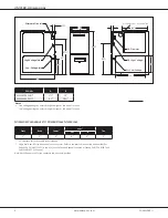
AMVS80-U Dimensions

28”

A

B

1¾”

33⅜”

23

5⁄16

1

7⁄16

13¼”

20”

27⅞”

Alt. Gas Inlet

Alt. High Voltage

Alt. Low Voltage

Alternate Gas Inlet

High-Voltage Inlet

Low-Voltage Inlet

Alt. Flue Outlet — Horizontal Left

19½”

23”

15”

Minimum Clearances to Combustible Materials

Sides

Rear

Front¹

Vent²

Top

SW

B

1”

0”

3”

6”

1”

1”

¹  24” clearance for serviceability recommended.
²  Single Wall Vent (SW) to be used only as a connector. Refer to the latest editions of the National Fuel Gas 

Code NFPA 54/ ANSI Z223.1 (in the USA) and the Canada National Standard of Canada, CAN/CSA B149.1 and 

CAN/CSA B142.2 (in Canada).

Note: AMVS80 approved for line contact in the horizontal position.

Model

A

B

AMVS800604BU*

17½”

16”

AMVS800805CU*

21”

19½”

Notes

• 

Line voltage wiring can enter through the right or left side of furnace. 


Low-voltage wiring can enter through the right or left side of furnace.

Summary of Contents for AMVS80-U

Page 1: ...J NOx emission limit in SCAQMD Rule 1111 and SJVUAPCD Rule 4905 EMI line filter kit must be installed It is intended for field installation only on VS model Bluetooth capable Ultra Low NOx Gas Furnace...

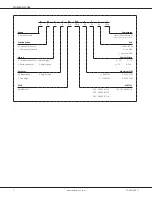
Page 2: ...on NOx M Upflow Horizontal N Natural Gas C Downflow Horizontal X Low NOx U Ultra Low NOx Motor Cabinet Width V Variable Speed ECM ComfortBridge A 14 C 21 E Multi Speed ECM S Single Speed B 17 D 24 Gas...

Page 3: ...ly For altitudes 4500 above sea level see installation manual DOE AFUE based upon Isolated Combustion System ICS Minimum Circuit Ampacity 1 25 x Circulator Blower Amps ID Blower amps Wire size should...

Page 4: ...ance for serviceability recommended Single Wall Vent SW to be used only as a connector Refer to the latest editions of the National Fuel Gas Code NFPA 54 ANSI Z223 1 in the USA and the Canada National...

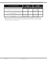
Page 5: ...d Heating CFM Expected Temperature Rise 1760 MAX CAPABLE CFM 25 1760 MAX CAPABLE CFM 40 Note To Set Heating CFM Using Push Buttons 1 Scroll using Left or Right push buttons until gAF appears on the 7...

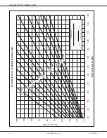
Page 6: ...HR x 1000 BTU OUTPUT vs TEMPERATURE RISE CHART TEMPERATURE RISE 600 CFM 700 900 1000 1100 1200 1400 1600 1800 2000 2200 2400 CFM FORMULAS BTU OUTPUT CFM x 1 08 x RISE RISE BTU OUTPUT 1 08 CFM 800 Tem...

Page 7: ...SWITCH ID BLOWER PRESSURE OR SERVICING WIRING EQUIPMENT GND ON SOME MODELS INTERNAL TO PROT DEVICE INTEGRATED CONTROL PK C USE COPPER CONDUCTORS ONLY AT LEAST 105 IT MUST BE REPLACED WITH WIRING MATER...

Page 8: ...uring Company L P Houston Texas Accessories Model Description MVK 01 Masonry Vent Kit TK 400 Twinning Kit Upflow applications only Minimum Filter Sizes Model AMVS80 0604BU AMVS80 0805CU Filter Size in...

Reviews: