TAS12-AS1 &TAS12P-AS1 Installation Instructions
PUD3677R1-0
For Assistance: [email protected] +1 (909) 591-8431
Page 5
Installation Instructions
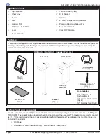
Pedestal Installation
Pencil
Pedestal
Base
⅝” Concrete Drill Bit
⅜" Concrete
Anchor
Threaded
Side Down
1. Determine where the pedestal will be installed. Once
the installation location has been determined, use a
chalk line to mark the centerline of the pedestal base
[Figure 1].
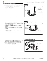
2. Place the pedestal base over the intersecting lines.
3. Mark the center location of all four anchor holes for
the pedestal base [Figure 2]. Set aside the pedestal
base.
4.
Using a ⅝" concrete drill bit, drill four anchor holes,
3" in depth, at the center of each marked location
[Figure 3].
The anchor holes must be clean before installing the
anchor bolts. If the anchor holes are not clear of debris,
the anchor bolts may not tighten correctly.
5. Insert one anchor into each drilled hole [Figure 3].
The threaded end of the anchor must be inserted into
the hole first. Use a hammer to tap the anchor into
place, if needed. Ensure that the anchors are flush
with the concrete floor.
5.50"
4.50"
CL
CL
NOTE
NOTE
Slab Requirements
• The slab must be a minimum of 4" thick. The
pedestal may only be installed on concrete.
• Do not install the pedestal on asphalt.
Space Requirements
•
Refer to the Plan, Elevation and Footprint drawings
in Appendix A for product dimensions.
•
The pedestal box lid (with TAS12 unit mounted)
requires 18" of lateral clearance to fully open.
•
The printer box door requires 21" of lateral
clearance to fully open (TAS12P-AS1 only).
Depending on the configuration ordered, the printer box
door may open from the right- or left-hand side.
Fig. 3
Inserting Anchors
Fig. 2
Marking & Drilling Anchor Holes
Fig. 1
Pedestal Base Dimensions


