


Installation Instructions
1170 N Red Gum St, Anaheim, CA 92806
© ALUZ All Rights Reserved. ALUZ reserves the right to make changes or withdraw specifi cations without prior notice.
aluz.lighting
866.ALUZ.LTG | 714.535.7900
A1 Series
|
Surface
ZIBI
Pivot RGBW
(A1-ZIBI-PVT-RGBW)
Page 6 of 11
4 / 29 / 2022 / Rev 2
Bottom Mount Adjustable Arm
(A1-ZIBI-PVT-AA-BM-X)
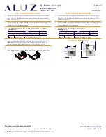
ASSEMBLED DIMENSIONS
SPACING DIAGRAMS
4’
3”
3”
3’6”
Mounting
Arms
Example: 4’ Run
4’
3”
3”
3’6”
Mounting
Arms
4’
3”
3”
3’6”
8’
Example: 8’ Run
4’
3”
3”
3’6”
Mounting
Arms
3’
3”
3”
2’6”
2’
3”
3”
1’6”
9’
Example: 9’ Run
Set Screw
Mounting Bracket
Locking Hole
Locking Bump
Set Screw
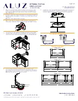
1
Measure area where luminaire will be installed. Use a laser line to create
a reference line along installation area, ensuring consistent alignment of
mounting arms. Mark location where each mounting arm will be installed
along reference line.
5
Loosen set screw until the mounting plate can move freely. Turn the
mounting plate until desired angle is achieved, then mate the locking bump
with locking hole. Tighten set screw until mounting plate is secured in place.
Note:
Refer to Angle Increments diagram next page.
2
Determine number of mounting arms needed. Use a minimum of 2 mounting
arms per luminaire. Mount arms 6” from center of mounting plate to the end
of luminaire.
Note:
Refer to Spacing Diagrams on next page.
3
Mark location where mounting arms will be installed. Screw arm base to
surface using countersink screws of appropriate type and length for surface.
4
Secure luminaire to mounting arms by snapping luminaire into mounting
clips, then install set screws to secure luminaire to clips. Ensure luminaire is
secured in place and spacing is accurate according to the Spacing Diagrams.
Shrink Tube
Apply Heat
2”
6
If applicable, connect disconnects between luminaires. Slide shrink tube over
connectors and apply heat. The shrink tube will shrink down, sealing the
connectors. Apply silicone around sealed connectors for a stronger seal.
2.0”
5.62”
X
With Louver
2.0”
4.61”
X
Without Louver


