


Installation Instructions
1170 N Red Gum St, Anaheim, CA 92806
© ALUZ All Rights Reserved. ALUZ reserves the right to make changes or withdraw specifi cations without prior notice.
aluz.lighting
866.ALUZ.LTG | 714.535.7900
A1 Series
|
Surface
ZIBI
Pivot RGBW
(A1-ZIBI-PVT-RGBW)
Page 3 of 11
4 / 29 / 2022 / Rev 2
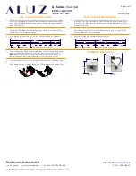
Mounting Clips
8’
3” Gap
Mounting Clip
Junction between luminaire segments
20’
8’
4’
8’
3” Gap
Mounting Clip
Junction between luminaire segments
20’
8’
4’
1
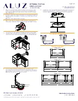
Measure area where luminaire will be installed. Use a laser line to create
a reference line along installation area, ensuring consistent alignment of
mounting clips. Mark location where each mounting clip will be installed
along reference line.
2
Use 1 mounting clip every 2’, rounded up. Use a minimum of 2 mounting clips
per luminaire segment. For vertical applications, create a stopper at the
bottom of the run to prevent sliding.
5
Screw mounting clips to surface, then snap luminaire into mounting clips.
Install set screws to each mounting clip, if applicable. Set screws are required
for downward facing, outward facing, and vertically mounted applications.
3
Use a mounting clip at the junction between two luminaire segments.
Example:
20’ Run.
4
Lay mounting clips along reference line and pre-drill using an appropriate
drill bit for surface material and screw size. Typical screw size is 8/32 x 1”.
Note:
Allow 1/4” clearance on each side of mounting clip to account for
lateral expansion. Only install mounting clips on flat, even surfaces.
3
Space mounting clips evenly throughout the run.
Example:
20’ Run.
2
Use 1 mounting clip every 2’, rounded up. Use a minimum of 2 mounting clips
per luminaire segment. For vertical applications, create a stopper at the
bottom of the run to prevent sliding.
1
Measure area where luminaire will be installed. Use a laser line to create
a reference line along installation area, ensuring consistent alignment of
mounting clips. Mark location where each mounting clip will be installed
along reference line.
DRY LOCATION APPLICATIONS
WET LOCATION APPLICATIONS
ASSEMBLED DIMENSIONS
2.56”
2.90”
0° Tilt
3.54”
4.13”
90° Tilt


