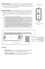
Alula RE607 Quick Start Manual Download Page 2

 External Contacts 

can be installed by routing the wires through 

the back of the enclosure. A thinned area in the enclosure must be 

punched out with a screwdriver to allow the wires through. After 

routing and connecting the wires, reseal the hole with silicone 

caulk. 

•  Do not use end-of-line resistors.

•  Wire contacts to one or both outside terminals using the 

center terminal as a shared common.

•  The sensor defaults to use normally closed contacts (alarm 

condition when contact is open).

•  To reprogram external inputs, set both externals to the 

desired non-alarm state and restart (remove and reinstall 

battery) the device 3 times while holding the tamper 

switch. 

Thinned area for external 

contact wires

Removal Tamper


is implemented by screwing the provided screw 

with rubber washer through the removal tamper screw hole in the 

base and into the mounting surface. Remove the battery for access 

to the removal tamper screw hole.

Removal tamper 

screw hole


Pro Tips

Metal installs

 should include pre-drilling holes before using 

screws to secure the mounting plate and magnet. 

Wireless performance

 is optimized when mounted near the 

top of the gate or door in a vertical orientation.

Summary of Contents for RE607

Page 1: ...racter serial number on the interactive service provider s web portal External contacts can be added on the interactive service provider s web portal Install by first attaching the mounting plate and magnet to a door window or fence using screws provided or cable ties not provided Make sure to align the alignment marks on the sensor and magnet when mounting Finish by latching the sensor to the mou...

Page 2: ... reprogram external inputs set both externals to the desired non alarm state and restart remove and reinstall battery the device 3 times while holding the tamper switch Thinned area for external contact wires Removal Tamper is implemented by screwing the provided screw with rubber washer through the removal tamper screw hole in the base and into the mounting surface Remove the battery for access t...

Page 3: ...es 9 02 cm 3 27 inches 8 31 cm 3 33 inches 8 46 cm Ferromagnetic Surface e g Iron Nickel etc Nominal Mounting Distance X Axis Make Break Y Axis Make Break Z Axis Make Break 1 90 inches 4 83 cm 2 00 inches 5 08 cm 2 05 inches 5 21 cm 2 50 inches 6 35 cm 3 00 inches 7 62 cm 2 32 inches 5 89 cm 2 37 inches 6 02 cm Sensitivity can be adjusted by moving the magnet in the closed position farther away fr...

Page 4: ...subject to the following two conditions 1 This device may not cause harmful interference 2 This device must accept any interference that may be received including interference that may cause undesired operation Changes or modifications not expressly approved by Alula could void the user s authority to operate this equipment FCC ID U5X RE607 Specifications subject to change without notice Physical ...

Reviews: