- 2 -
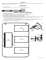
TDMD2 - DMP Door Backplane
DMP
714-8 0r 714-16
DMP
714-8 0r 714-16
DMP
714-8 0r 714-16
DMP
XR150 orXR550
Bracket
Pem
Standoff
DMP Board
Backplane
Pan Head
Screw
Step 1
Step 2
Pan Head Screw
Back of TDMD2
Lock Nut
Step 3
XR150 or XR550
Mounting Bracket
XR150 or XR550
Fig. 1a
Fig. 1b
Overview:
TDMD2 accommodates a combination of the following DMP boards: one (1) XR150 or XR550 board and up to three (3) multi-zone 714
expansion boards for up to forty-eight (48) zones.
Specifications:
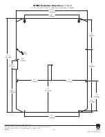
• 16 Gauge backplane.
Dimensions (H x W x D): 23.75” x 18.125” x 0.3125” (603.3mm x 460.3mm x 7.9mm).
Hardware:
TDMD2: Configuration of DMP Boards:
1.
Mounting 714 expansion boards:
a. Fasten standoffs (provided) into a corresponding pem configuration of backplane (Fig. 1, pg. 2).
b. Mount boards to standoffs utilizing 5/16” pan head screws (provided) (Fig. 1a, pg. 2).
2.
Mounting XR150 or XR550 board utilizing a bracket (provided):
a. Push two (2) pan head screws (provided) through the corresponding holes from the back of the backplane (Fig. 1b, pg. 2, Step 1).
b. Mount bracket with slits to the left on screws and secure it with two (2) lock nuts (provided) (Fig. 1b, pg. 2, Step 2).
c. Fasten two (2) standoffs (provided) onto the mounting pems.
d. Orient DMP XR150 or XR550 so the terminal block is to the left. Slide the opposite edge of the board into the bracket’s slits
(Fig. 1b, pg. 2, Step 3) and secure the board to standoffs with two (2) pan head screws (provided).
3. Mount backplane to enclosure’s door with hardware.
Nylon Standoff | 5/16” Pan Head Screw | Lock Nut
Fig. 1


