background image


- 4 -  

Trove2/Mercury Fused Kits Installation Guide

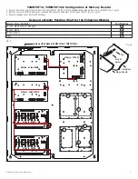
T2MK7F8, T2MK7F8Q: Configuration of Mercury Boards:

1.  Fasten snap on spacers onto metal pems configuration (A), (B), (C) or (D) of backplane depending on the access controller 

(Fig. 3, pg. 4)

.

2.  Position access controller module over corresponding spacers and depress onto snap on spacers 

(Fig. 3a, pg. 4)

.

3.  Mount backplane to enclosure with hardware.

Access Controller Position Chart for the Following Models:

Mercury Access Controller

Pem Mounting

EP1502, MR52, MR16IN, MR16OUT

A

EP2500, MUX8

B

EP1501, MR51e

C

MR50

D

Fig. 3

B

B

A

B

C

C

C

C

C

D

D

B

A

A

A

Altronix LINQ2 Module (T2MK3F8Q)

NC  C  NO  NC C  NO

AC FAIL

BAT FAIL

TRIGGER

AC DC

AC1

EOL

NO

GND

SUPERVISED

RESET

+AUX-

-  BAT  

+-

  DC  

+

L     G     N

OFF - 24V
ON - 12V

ON

Altronix - eFlow104NB

+ INP1 

-- 

PWR1 +

PWR1 +

OFF

IN1

IN2

Out1

<

1 off 

2>

PWR2 +

PWR2 +

COM ---


+ INP2 

-- 

IN2 Fuse

IN1 Fuse

Common   Power   Outputs (NEG)

N

P

OUT1

OUT2

OUT3

OUT4

OUT5

OUT6

OUT7

OUT8


8

10

10

3

3

3

3

3

3

3

3

Out2

<

1 off 

2>

Out3

<

1 off 

2>

Out4

<

1 off 

2>

Out5

<

1 off 

2>

Out6

<

1 off 

2>

Out7

<

1 off 

2>

Out8

<

1 off 

2>

Altronix - PDS8

Altronix VR6 is mounted under PDS8

OUTPUT 1     OUTPUT 2         OUTPUT 3         OUTPUT 4          OUTPUT 5        OUTPUT 6         OUTPUT 7        OUTPUT 8

NC  C  NO COM NC C NO COM  NC  C  NO COM NC C NO COM  NC  C  NO COM NC C NO COM  NC  C NO COM NC C NO COM

 IN  GND IN GND IN GND IN GND

IN  GND IN GND IN  GND IN GND

1            2           3          4

5           6           7           8

 INPUT

TRIGGER

10A 250V

+INP-  T + RET-

NO  C   NC

FACP            INTERFACE

Power   Contro

l

-      +      -      

+

F1                   F2                  F3                   F4                   F5                   F6                   F7                   F8

MAIN

TRG

FACP

1     2     3     4

1     2     3     4

O N

O N

1     2     3     4

1     2     3     4

O N

O N

Altronix - ACM8

Snap On

Spacer

Mercury Board

Backplane

Pem

Fig. 3a

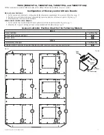
Summary of Contents for TROVE T2MK3F4

Page 1: ...ut Power Distribution Module 16 Door Kits T2MK75F16 Fully assembled kit includes Trove2 enclosure with TM2 Altronix Mercury backplane and TMV2 door backplane 1 eFlow104NB and 1 eFlow102NB Power Supply...

Page 2: ...250V 3 5A 250V 5A 250V T2MK77F16 9 6 3A 250V 15A 32V 20 17 26 4 20 28 26 4 20 17 26 4 20 28 26 4 24VDC 9 2A 16 2 5 10A 250V 2 5A 250V 10A 250V 3A 250V T2MK77F16Q P 9 6 3A 250V 15A 32V 20 17 26 4 20 2...

Page 3: ...N2 Out1 1 off 2 PWR2 PWR2 COM INP2 IN2 Fuse IN1 Fuse Common Power Outputs NEG N P OUT1 OUT2 OUT3 OUT4 OUT5 OUT6 OUT7 OUT8 1 2 3 4 5 6 7 8 10 10 3 3 3 3 3 3 3 3 Out2 1 off 2 Out3 1 off 2 Out4 1 off 2 O...

Page 4: ...GND SUPERVISED RESET AUX BAT DC L G N OFF 24V ON 12V ON Altronix eFlow104NB INP1 PWR1 PWR1 OFF IN1 IN2 Out1 1 off 2 PWR2 PWR2 COM INP2 IN2 Fuse IN1 Fuse Common Power Outputs NEG N P OUT1 OUT2 OUT3 OU...

Page 5: ...IN GND IN GND IN GND IN GND IN GND IN GND IN GND 1 2 3 4 5 6 7 8 INPUT TRIGGER 10A 250V INP T RET NO C NC FACP INTERFACE Power Control F1 F2 F3 F4 F5 F6 F7 F8 MAIN TRG FACP 1 2 3 4 1 2 3 4 O N O N 1...

Page 6: ...2 3 4 5 6 7 8 INPUT TRIGGER 10A 250V INP T RET NO C NC FACP INTERFACE Power Control F1 F2 F3 F4 F5 F6 F7 F8 MAIN TRG FACP 1 2 3 4 1 2 3 4 O N O N 1 2 3 4 1 2 3 4 O N O N Altronix ACM8 OUTPUT 1 OUTPUT...

Page 7: ...7 2 Position access controller module over corresponding spacers and depress onto snap on spacers Fig 6a pg 7 3 Mount backplane to enclosure with hardware Altronix Sub Assemblies and or Adapters 1 Fas...

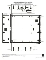
Page 8: ...5 4mm 27 685 8mm 1 5 38 1mm 2 00 50 8mm 2 00 50 8mm 3 5 88 9mm 3 5 88 9mm 21 50 546 1mm 5 25 133 35mm 5 25 133 35mm 6 25 158 8mm 1 25 31 8mm 0 85 21 6mm 0 5625 14 3mm 2 415 61 3mm 0 685 17 4mm 1 77 45...

Reviews: