background image

ReServWPV 

 - 7 -

Wall Mount Installation

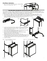
1-  Place unit at desired location and secure with mounting

 screws 

(not included) (Fig. 4, pg. 7).


Fig. 4

Pole Mounting Using Optional Pole Mount Kit PMK1 

(not included)

:

This installation should be made by qualified service personnel. This product contains no serviceable parts. PMK1 is in-

tended for use with Altronix outdoor rated power supplies or accessories housed in WP1, WP2, WP3 and WP4 enclosures. 

Brackets are designed for use with the Wormgear Quick Release Straps (two included).

1.  Thread one (1) wormgear quick release strap through the slots on the back of a mounting bracket (Fig. 5, pg. 7).

2.  Once the desired height of the top Pole Mount bracket is achieved, tighten the straps down by sliding open end


of the strap through the locking mechanism on the strap, then tighten the screw with


flat head screwdriver or 5/16” hex socket driver (Fig. 6, pg. 7).

3.  Attach the bottom bracket to the enclosure by inserting bolts through the


flange of the enclosure and into the bracket, tightening bolts with a


7/16” hex socket (Fig. 8, pg. 7).

4.  Thread the second wormgear quick release strap through the slots on the


back of the bottom mounting bracket (Fig. 8, pg. 7).

5.  Mount enclosure onto the top bracket by inserting bolts through


flange of the enclosure and into the bracket,


tightening bolts with a 7/16” hex socket (Fig. 9, pg. 7).

6.  Tighten the straps of the bottom bracket down by sliding the open end of


the strap through the locking mechanism on the strap, then tighten screw


with flat head screwdriver or 5/16” hex socket driver (Fig. 9/9a, pg. 7).

7.  Clip excess straps.

Fig. 9 - 2” to 8”(50.8mm to 203.2mm) 

Fig. 9a - 5” (127mm) square pole


diameter round pole

Fig. 5

Fig. 6

Fig. 7

Fig. 8

Summary of Contents for ReServ1WPV

Page 1: ...utputs 4A total supply current 24VAC and 2A total supply current 12VDC PTC protected power limited outputs ReServ2WPV Sixteen 16 true sine wave regulated 24VAC outputs 4A total supply current PTC protected power limited outputs ReServ3WPV Sixteen 16 regulated 12VDC outputs 8A total supply current PTC protected power limited outputs More than just power ...

Page 2: ... with the top and bottom holes of the enclosure flange Mount unit in the desired location with the appropriate fasteners Pgs 7 and 8 Secure enclosure to earth ground Note This product needs to be secured to the building pole before operation 5 Connect AC power mains to the terminals marked L and N Figs 2 3 pg 5 6 Use 18 AWG or larger for all power connections Battery output Figs 2 3 pg 5 6 Use 18 ...

Page 3: ...y outputs 12 The power LEDs on the unit for Outputs 1 16 will illuminate when AC power is present Figs 2 3 pg 5 6 Note If any of the power LEDs are not illuminated the cause may be due to the following a AC mains and battery fail b One 1 or more power output PTCs are tripped due to a short circuit or overload condition c Unit damaged defective To reset the PTC 1 Disconnect corresponding camera dev...

Page 4: ...esent terminals marked NO and C are open NC and C are closed When loss of AC occurs terminals marked NO and C are closed NC and C are open BAT FAIL NO C NC Form C dry contacts used to signal low battery voltage or loss of battery voltage Under normal conditions terminals marked NO and C are open NC and C are closed During a trouble condition terminals marked NO and C are closed and NC and C are op...

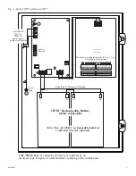
Page 5: ...A power mains non power limited power limited For outputs configuration refer to Step 9 Pg 3 of Installation Instructions Note Two 2 12VDC rechargeable batteries connected in series required Supervised Non power limited CAUTION Risk of explosion if battery is replaced by an incorrect type Dispose of used batteires according to the instructions 12VDC Rechargeable Battery order separately ...

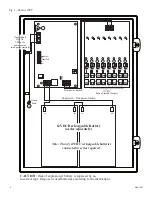
Page 6: ...k of explosion if battery is replaced by an incorrect type Dispose of used batteires according to the instructions 12VDC Rechargeable Battery order separately P N 1 OUT 2 1 2V adjust P N 3 OUT 4 3 4V adjust P N 5 OUT 6 5 6V adjust P N 7 OUT 8 7 8V adjust P N 9 OUT 10 9 10V adjust P N 11 OUT 12 11 12V adjust P N 13 OUT 14 13 14V adjust P N 15 OUT 16 15 16V adjust 9 10 11 12 13 14 15 16 1 2 3 4 5 6 ...

Page 7: ...the strap through the locking mechanism on the strap then tighten the screw with flat head screwdriver or 5 16 hex socket driver Fig 6 pg 7 3 Attach the bottom bracket to the enclosure by inserting bolts through the flange of the enclosure and into the bracket tightening bolts with a 7 16 hex socket Fig 8 pg 7 4 Thread the second wormgear quick release strap through the slots on the back of the bo...

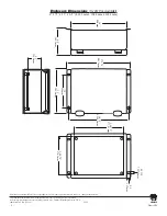
Page 8: ...718 567 8181 fax 718 567 9056 website www altronix com e mail info altronix com Lifetime Warranty Made in U S A IIReServWPV Rev 021412 F16P 16 406mm 6 5 165 1mm 17 375 441 3mm 10 254mm 16 75 425 45mm 12 304 8mm 10 875 276 2mm 14 875 377 83mm 0 3125 7 9375mm 0 5 12 7mm 4 5 114 3mm Enclosure Dimensions H x W x D approximate 17 375 x 12 x 6 5 441 3mm x 304 8mm x 165 1mm MEMBER ...

Reviews: