background image

1

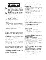
SAFETY RELATED SYMBOLS

CAUTION

RISK OF ELECTRIC SHOCK

DO NOT OPEN

This symbol, wherever used, alerts you to the pre-
sence of un-insulated and dangerous voltages with-
in the product enclosure. These are voltages that
may be sufficient to constitute the risk of electric
shock or death.

Protective Ground Terminal

AC mains (Alternating Current)

Hazardous Live Terminal

ON:

Denotes the product is turned on.

This symbol, wherever used, alerts you to impo-
rtant operating and maintenance instructions.
Please read.

OFF:

Denotes the product is turned off.

WARNING

Describes precautions that should be observed to
prevent the possibility of death or injury to the user.

CAUTION

Describes precautions that should be observed to
prevent damage to the product.

Power Supply

Ensure that the mains source voltage (AC outlet)
matches the voltage rating of the product. Failure
to do so could result in damage to the product and
possibly the user.

Unplug the product before electrical storms occur
and when unused for long periods of time to reduce
the risk of electric shock or fire.

External Connection

Always use proper ready-made insulated mains
cabling (power cord). Failure to do so could result
in shock/death or fire. If in doubt, seek advice from
a registered electrician.

Do Not Remove Any Covers

Within the product are areas where high voltages
may present. To reduce the risk of electric shock do
not remove any covers unless the AC mains power
cord is removed.

Covers should be removed by qualified service
personnel only.

No user serviceable parts inside.

Fuse

To prevent fire and damage to the product, use only

the recommended fuse type as indicated in this
manual. Do not short-circuit the fuse holder. Before
replacing the fuse, make sure that the product is
OFF and disconnected from the AC outlet.

Protective Ground

Before turning the product ON, make sure that it is
connected to Ground. This is to prevent the risk of
electric shock.

Never cut internal or external Ground wires. Likewise,
never remove Ground wiring from the Protective
Ground Terminal.

Operating Conditions

Always install in accordance with the manufacturer's
instructions.

To avoid the risk of electric shock and damage, do
not subject this product to any liquid/rain or moisture.
Do not use this product when in close proximity to
water.

Do not install this product near any direct heat source.

Do not block areas of ventilation. Failure to do so
could result in fire.

Keep product away from naked flames.

IMPORTANT SAFETY INSTRUCTIONS

Read these instructions

Follow all instructions

Keep these instructions. Do not discard.

Heed all warnings.

Only use attachments/accessories specified by the
manufacturer.

Power Cord and Plug

Do not tamper with the power cord or plug. These are
designed for your safety.

Do not remove Ground connections!

If the plug does not fit your AC outlet seek advice from
a qualified electrician.

Protect the power cord and plug from any physical
stress to avoid risk of electric shock.

Do not place heavy objects on the power cord. This
could cause electric shock or fire.

Cleaning

When required, either blow off dust from the product
or use a dry cloth.

Do not use any solvents such as Benzol or Alcohol.
For safety, keep product clean and free from dust.

Servicing

Refer all servicing to qualified service personnel only.

Do not perform any servicing other than those instruc-
tions contained within the User's Manual.

WARNING

Summary of Contents for X23

Page 1: ...User s Manual LTO R www altoproaudio com Version 2 0 Dec 2002 English 2 WAY STEREO 3 WAY MONO ACTIVE CROSSOVER X23 ...

Page 2: ...y the recommended fuse type as indicated in this manual Do not short circuit the fuse holder Before replacing the fuse make sure that the product is OFF and disconnected from the AC outlet Protective Ground Before turning the product ON make sure that it is connected to Ground This is to prevent the risk of electric shock Never cut internal or external Ground wires Likewise never remove Ground wir...

Page 3: ... the art algorithms which have been developed by our Because we are convinced you are the most important member of LTO AUDIO TEAM and the one confirming the quality of our job we d like to share with you our work and our dreams pay attention to your suggestions and Following this idea we create our products and we will create the new ones From our side we guarantee you and we will guarantee you al...

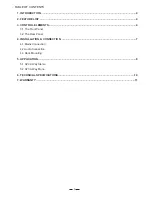
Page 4: ...T 4 3 CONTROL ELEMENTS 4 3 1 The Front Panel 3 2 The Rear Panel 4 INSTALLATION CONNECTION 7 4 1 Mains Connection 4 2 Audio Connection 4 3 Rack Mounting 5 APPLICATION 8 5 1 X23 2 Way Stereo 5 2 X23 3 Way Mono 6 TECHNICAL SPECIFICATIONS 10 7 WARRANTY 11 ...

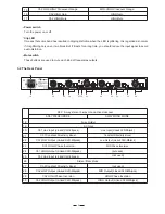
Page 5: ...ersion way stereo and 3 way mono speaker systems LTO 0 0 700 300 170 90 0 0 HIGH GAIN INPUT LEVEL INPUT LEVEL XOVER FREQ XOVER FREQ LOW GAIN LOW GAIN 10 1 MUTE RANGE MUTE OFF 80 1K OFF 6 OFF 6 6 0 700 300 170 90 0 0 HIGH GAIN HIGH GAIN INPUT LEVEL CLIP XOVER FREQ XOVER FREQ LOW GAIN MID GAIN POWER 2W STEREO 3W MONO 10 1 RANGE OFF MUTE MUTE 80 1K OFF 6 OFF 6 CLIP 6 HIGH LOW CHANNEL 2 CHANNEL 1 HIGH...

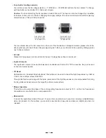
Page 6: ...h These buttons are used to mute each kind of frequencies outputs 5 HIGH Gain HIGH Mute Ch2 HIGH Gain Ch2 HIGH Mute Ch2 C Range LOW HIGH rossover MID HIGH Crossover Range 19 18 30 29 28 26 27 25 24 22 23 21 20 Clip LED 110 120V 220 240V HIGH PHASE HIGH PHASE MODE CD BOOST CD BOOST STEREO MONO CHANNEL 2 CHANNEL 1 HIGH OUT 1 NOT USED HIGH OUT 2 HIGH OUT LOW OUT 2 MID OUT INPUT 2 NOT USED LOW OUT1 LO...

Page 7: ...essed On the contrary you are able to operate it as 2 way stereo crossover High Low when it is released CD Boost 3 5kHz then 6dB per octave till 22 5kHz Caution The fuse protecting the AC supplies circuits of this unit The fuse can only be changed by a qualified technician in the event of a fault or changing the supply voltage If the fuse continues to blow after replacing The inputs and outputs ca...

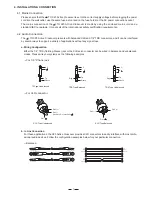
Page 8: ...leeve Tip Ring Sleeve Tip Ring Sleeve 1 2 3 1 2 3 1 2 3 TIP RING SLEEVE SLEEVE RING TIP TIP RING SLEEVE 2 1 3 1 2 3 1 2 3 Please ensure that the LTO X23 Active Crossover is set to the correct supply voltage before plugging the power cord into the wall outlet use the same fuse as marked on the fuse holder at the AC power connection socket The mains connection of the LTO X23 Active Crossover is made...

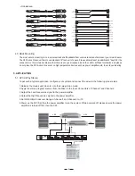
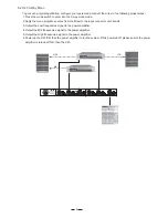
Page 9: ...equencies signal to the power amplifier 5 Set LOW HIGH Crossover Range of channel1 and channel2 to 10 6 Power up the X23 first then the power amplifier to run the system While powered off please ensure the power amplifier is turned off first then the X23 HIGH LOW 110 120V 220 240V HIGH PHASE HIGH PHASE MODE CD BOOST CD BOOST STEREO MONO CHANNEL 2 CHANNEL 1 HIGH OUT 1 NOT USED HIGH OUT 2 HIGH OUT L...

Page 10: ...mplifier 6 Power up the X23 first then the power amplifier to run the system While powered off please ensure the power amplifier is turned off first then the X23 110 120V 220 240V HIGH PHASE HIGH PHASE MODE CD BOOST CD BOOST STEREO MONO CHANNEL 2 CHANNEL 1 HIGH OUT 1 NOT USED HIGH OUT 2 HIGH OUT LOW OUT 2 MID OUT INPUT 2 NOT USED LOW OUT1 LOW OUT INPUT 1 INPUT PUSH 2 1 3 NEW TIDE PUSH 2 1 3 NEW TI...

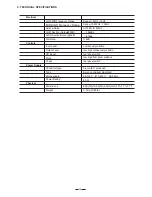
Page 11: ...194 5 D 44 H mm 19 7 7 1 7 3 1Kg 6 84lb LOW MID Frequency Range MID HIGH Frequency Range HUM Noise LOW Section Output 0dB HIGH Section Output 0dB S N Ratio Range 1 80Hz 1KHz Range 10 800Hz 10KHz AV 0dB fc 800Hz 106dBu 97dBu 118dB Electrical Power Supply Connector type Type Mains supply Power Rating 3 pole IEC grounded Servo controlled stabilized 8 5W 95 120V 210 240V 60 50Hz 10 6 TECHNICAL SPECIFI...

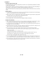
Page 12: ...d LTO of 1 year from the purchase date if you have completed the Warranty Registration Card in time 3 3 During the warranty service may repair or replace this product at its own option at no charge to you for LTO parts or for labor in accordance with the right side of this limited warranty 3 4 This warranty does not apply to the damages to this product that occurred as the following conditions Nor...

Page 13: ...ll rights reserved to ALTO Mobile Due to continued development in response to customer feedback product features specifications and or internal external design may be changed without prior notice No photocopying translation or reproduction of any part of this user manual is allowed without prior written permission Copyright 2004 Seikaku Technical Group Limited c NF00878 1 0 ...

Reviews: