UT260-102 UNDER TABLE 4X1
HDMI SWITCHER
User’s Guide
400-0476-001
1
Welcome!
Everyone at Altinex greatly appreciates your purchase of the
UT260-102. We are confident that you will find it to be reliable
and easy to use. If you need support, please do not hesitate to
call us at 714-990-2300.
At Altinex, we are committed to developing unique and state of
the art Signal Management Solutions
®
for demanding audiovisual
installations. Welcome to the Altinex family of satisfied customers
around the world!
1. Precautions and Safety Warnings
These instructions are to ensure the reliable operation of
your UT260-102 and to prevent fire and shock hazards.
Please read them carefully and heed all warnings.
1.1 General
Qualified ALTINEX service personnel or their authorized
representatives must perform all service.
1.2 Installation Precautions
To prevent fire or shock, do not expose this unit to water or
moisture. Do not place the UT260-102 in direct sunlight, near
heaters or heat-radiating appliances, or near any liquid.
Exposure to direct sunlight, smoke, or steam can harm
internal components.
Handle carefully; dropping or jarring can cause damage.
Do not pull any cables that are attached to the UT260-102.
1.3 Cleaning
Clean with a dry cloth only. Never use strong detergents
or solvents such as alcohol or thinner.
1.4 FCC Notice
This device complies with Part 15 of the FCC Rules.
Operation is subject to the following two conditions: (1) This
device may not cause harmful interference, and (2) this
device must accept any interference received, including
interference that may cause undesired operation.
This equipment has been tested and found to comply with
the limits for a Class B digital device, pursuant to Part 2 of
the FCC Rules. These limits are designed to provide
reasonable protection against harmful interference when the
equipment is operated in a commercial environment. This
equipment generates, uses, and can radiate radio frequency
energy and, if not installed and used in accordance with the
instructions found herein, may cause harmful interference to
radio communications. Operation of this equipment in a
residential area is likely to cause harmful interference in
which case the user will be required to correct the
interference at their own expense.
Any changes or modifications to the unit not expressly
approved by ALTINEX, Inc. could void t
he user’s authority to
operate the equipment.
2. Installation Procedures
Note:
Download and read the entire online manual to become familiar with the UT260-102 and for detailed information.
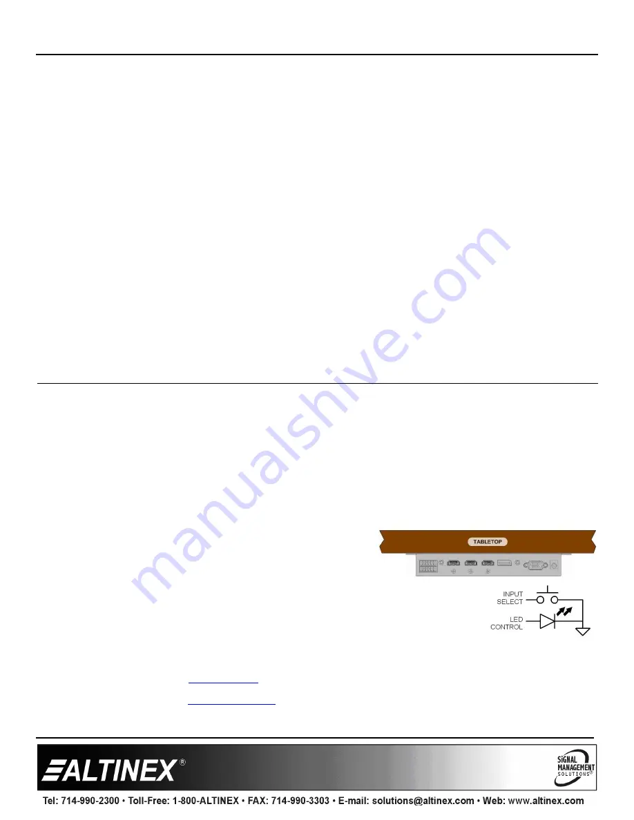
Step 1: The enclosure mounts under the table using the mounting brackets included.
Step 2: Connect input cables from the sources.
Step 3. Connect the digital output directly to the HDTV. If there is at least one input signal present, an image appears on the TV.
Step 4. Apply power to the unit using the power adapter provided.
Step 5. The UT260-102 is ready for use. Auto-switch is one of the default configuration settings. If a signal is removed, the switcher
automatically switches to another input if a signal is present.
Step 6. The UT260-102 may be controlled using RS232 commands from a
controller, or using simple momentary push button switches wired to
the terminal block on the rear panel. See the full user guide for details.
On the rear terminal block, there are input select controls, output LED controls,
and RS232 control pins.
The input select controls are activated using a momentary contact closure to ground to between each input
pin and ground. The LED output pins drive LEDs to indicate a signal is present (flashing) or active on the
output (solid), same as front panel LEDs. The RS232 controls can be used to control or configure the
UT260-102.
See the top label of the UT260-102 for details, or refer to the complete online manual.
3. Warranty and Return Policies
Please visit the ALTINEX website at
www.altinex.com
for details on warranty and return policies. In the case of a unit needing repair,
please complete a RMA (return material authorization) form located on the bottom left hand corner of the Altinex homepage. Once
completed, please email the form to
.


