Altimium SCA51TS User Manual Download Page 18

Compact Scaler Switcher (with PoH)                                                             


Altimium                                                            13                                    www.altimium.com 


4.2.4 CEC Function 

SCA51TS supports CEC, it can be turned on/ off by sending RS232 commands or OSD 
menu operations. The default setting is ON. 

Commands pertaining to CEC: 

“50686%” (enable CEC) and “50687%” (disable CEC) 

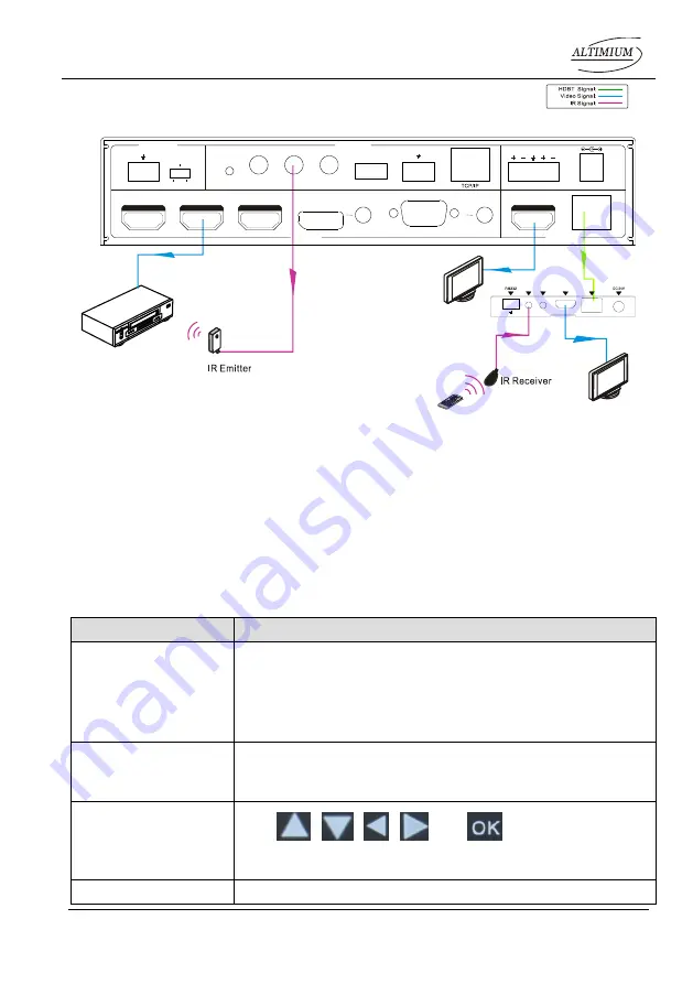
HDMI INPUT ports 1~3 support CEC, if the connected source devices also support CEC 
and their CEC are on, users can control the source device and display via the IR remote 
of SCA51TS.   

The working status related to CEC and STANDBY is showed as below: 

Situation 

Working Status 

CEC: on, Standby: on 

Press STANDBY button on IR remote, SCA51TS enters in 
standby mode, so do all HDMI source devices and display. 
Press STANDBY button again on IR remote, SCA51TS exits 
standby mode, the previous selected HDMI input source 
device and display start working too. 

CEC: on, Standby: off 

Press STANDBY button on IR remote, SCA51TS enters in 
standby mode, HDMI 1~3 source devices and display keep 
on. 

CEC: on 

Use 

  and 

  buttons on IR 

remote to control HDMI source device. 

CEC: off 

Unable to control HDMI source device and display through IR 

DVD

HDTV

48V

LINE

IR EYE

IR IN

IR OUT

MIC INPUT

MIC

FIRMWARE

  AUDIO OUT

L

R

RES RESET

RS232

Tx

Rx

L

R

 INPUTS

OUTPUTS

3-HDMI

2-HDMI

1-HDMI / MHL

4-DP

5-VGA

HDMI

HDBT

CONTROL

DC 24V 

IR OUT

IR IN

HDMI OUT

HDBT IN

Tx

Rx

HDBaseT Receiver

HDTV

IR Remote


Summary of Contents for SCA51TS

Page 1: ...SCA51TS Compact Scaler Switcher with PoH All Rights Reserved Version SCA51TS_2016V1 1 User Manual...

Page 2: ...knowledged as the properties of the trademark owner No part of this publication may be copied or reproduced without the prior written consent FCC Statement This equipment generates uses and can radiat...

Page 3: ...rain moisture or install this product near water Do not put any heavy items on the extension cable in case of extrusion Do not remove the housing of the device as opening or removing housing may expo...

Page 4: ...System Operations 10 4 1 Front Panel Buttons 10 4 1 1 Manual Switching 10 4 1 2 Auto Switching 10 4 1 3 Volume Adjusting 10 4 2 IR Control 11 4 2 1 IR Remote 11 4 2 2 Control far end device from local...

Page 5: ...PICTURE 27 4 4 3 SETUP 28 4 5 Web based GUI Control 29 4 5 1 Control Menu 29 4 5 2 Configuration Menu 31 4 5 3 RS232 Control Menu 33 4 5 4 Password Menu 34 4 5 5 Web based GUI Update 34 5 Specificatio...

Page 6: ...BaseT Receiver In addition SCA51TS can be controlled via front panel buttons IR remote RS232 commands and web based GUI 1 2 Features Compliant with HDMI1 4 HDCP2 2 Supports CEC with commands to enable...

Page 7: ...e 1 x VGA converting cable VGA to YPbPr 1 x HDBaseT Receiver TP411R 4K 2 x Mounting Ears with 4 screws for TP411R 4K 4 x Plastic Cushions for TP411R 4K 1 x RS232 cable 3 Pin phoenix connector to DB9 2...

Page 8: ...ty LED OSD menu button Press this button to enter or exit Auto switching mode in this mode select input source via front panel button is not available but RS232 command and IR remote are able to switc...

Page 9: ...een indicator will keeps blinking MIC INPUT MIC audio port connect to Microphone Dial switch including 3 level 48V phantom power mode connect with condenser microphone MIC mode connect with dynamic mi...

Page 10: ...CA51TS or other devices connected with HDBaseT Receiver TCP IP Ethernet port connect with PC to control SCA51TS via Web based GUI AUDIO OUTPUT Audio output port the audio comes from the input audio co...

Page 11: ...DP input port with DisplayPort cable and DP audio input port with audio cable Step3 Connect a VGA source device e g Laptop to VGA input port with VGA cable and VGA audio input port with audio cable S...

Page 12: ...ld connect with an IR transmitter For example When IR IN of SCA51TS connects with an IR receiver the IR transmitter must connect to IR OUT of HDBaseT Receiver The IR signal can be transmitted bi direc...

Page 13: ...icrophone There are two different connection methods 1 Unbalanced connection and connect to ground and connects to signal and connect to ground and connects to signal 2 Balanced connection connects to...

Page 14: ...to ground and connects to signal and connect to ground and connects to signal 2 Balanced connection connects to positive connects to negative and connects to ground 3 5 Application SCA51TS has a good...

Page 15: ...lable the unit will output the signal If not the unit will detect all the input signals wit priority from 1 HDMI MHL to 5 VGA When detected the first signal it will transfer to output Signal removing...

Page 16: ...ng button audio switched following the corresponding DP VGA Auto button Enter Exit auto switching mode Mute unmute audio VOL Volume adjusting button After pressing this button the volume adjusting men...

Page 17: ...m local 4 2 3 Control local device from remote Connect an IR emitter to IR OUT port on SCA51TS and connect IR receiver to the IR IN port on the HDBaseT Receiver the source devices can be control by th...

Page 18: ...ress STANDBY button on IR remote SCA51TS enters in standby mode so do all HDMI source devices and display Press STANDBY button again on IR remote SCA51TS exits standby mode the previous selected HDMI...

Page 19: ...sic Settings First to connect SCA51TS with all input devices and output devices needed then to connect it with a computer which is installed with RS232 control software Double click the software icon...

Page 20: ...Please set the parameters of COM number bound rate data bit stop bit and the parity bit correctly and then you are able to send command in Command Sending Area Parameter Configuration area Monitoring...

Page 21: ...t to YPbPr for 5 VGA input Input 5 Set Switch to YPbPr 50685 Set the signal format to AV C video for 5 VGA input Input 5 Set Switch to AV 50785 Enable auto switching Auto Switching 50786 Disable auto...

Page 22: ...0 720P Resolution 1280x720 50628 Set the output resolution to 1280X800 WXGA Resolution 1280x800 50629 Set the output resolution to 1920X1080 1080P Resolution 1920x1080 50620 Set the output resolution...

Page 23: ...able the mute icon of MIC audio display MIC Mute Icon disable 50764 Enable the mute icon of MIC audio display MIC Mute Icon enable 50765 Enable the freeze icon display Freeze Icon enable 50766 Disable...

Page 24: ...2 and far end RS232 Mode 2 RS232 Control Scaler 50714 Auto Switch Mode Disable the automatic power off function Auto Switch Mode Set no input to power off function Disable 50715 Auto Switch Mode Set t...

Page 25: ...off time to 5 minute Manual Switch Mode Set no input to power off time 5 minutes 50744 Manual Switch Mode Set the power off time to 10 minute Manual Switch Mode Set no input to power off time 10 minu...

Page 26: ...ess Sharpness xx xx 00 99 50640 Check the color temperature Color Temperature xx xx Cool Medium Warm User 50651 Check Volume Icon display status Volume Icon xxxx 50712 Check the audio input sources fo...

Page 27: ...osition Adjust Y XX 50673 Move the image down Output Position Adjust Y xx 50674 Stretch left from left side increase image width Output Width Adjust xx 50675 Pull right from left side decrease image w...

Page 28: ...ommand CEC cmd exit 50913 Source power on Source power on 50914 Source power off Source power off 50920 TV power on Display power on 50921 TV power off Display power off Note Screen output adjusting a...

Page 29: ...n present system Connect as below Control SCA51TS or 3rd party device from local 4 3 5 Control SCA51TS or 3rd party device form Remote Firstly according the following connection diagram to connect all...

Page 30: ...t panel 2 seconds or more Press MENU button on IR remote Send the command 50616 on RS232 Control Software Operation way Press direction buttons on front panel or IR remote to switch between menu optio...

Page 31: ...onent video signal Baud rate Set the baud rate for RS232 control and it support 2400 4800 9600 19200 38400 57600 115200 User EDID Load USB Insert the USB flash disk with EDID file to FIRMWARE port to...

Page 32: ...image contrast brightness color and sharpness Color Temperature Include Cool Medium Warm and User And only in User mode it is able to set values for Red Green and Blue RGB Aspect Ratio Include Native...

Page 33: ...Supports 7 languages including English default Chinese etc Restore Factory Default Restores to original system state Blending Includes Low Middle High and Off HDMI CEC Enable disable CEC and auto stan...

Page 34: ...ftware SCA51TS can be controlled via web based GUI It allows users to interact with SCA51TS through graphical icons and visual indicators Type 192 168 0 178 in your browser it will enter the log in in...

Page 35: ...e the best visual effect DP Click Audio to turn on off the DP external audio input Volume Click the corresponding positive negative button to increase decrease the volume of microphone audio or source...

Page 36: ...hen click Confirm Update Insert the USB flash disk with EDID file software updating file to FIRMWARE port and then click EDID Firmware to start update procedure Shutdown Timer NO Input Set the shutdow...

Page 37: ...k setting menu shown as below In this interface dynamic or static IP mode can be selected Under static IP mode IP address and subnet mask gateway can be set and make sure the IP addresses are differen...

Page 38: ...n as below Port Local port refers to the RS232 port of SCA51TS and the HDBT port refers to the RS232 port of HDBaseT Receiver Baud Rate The baud rate of local port is 9600 which can t be modified but...

Page 39: ...ased GUI Update Web based GUI for SCA51TS supports online update in http 192 168 0 178 100 Type the username and password the same as the GUI log in settings modified password will be available only a...

Page 40: ...200 1600x900 1360x768 1280x800 1280x720 1024x768 Standards Compliant with HDMI 1 4 HDCP2 2 Audio Audio Input 1 stereo audio input for DP 1 stereo audio input for VGA 1 Microphone audio Audio Input Con...

Page 41: ...r with PoH Altimium 36 www altimium com 1 RJ45 General Transmission Distance 1080P 70m Cat6 Temperature 0 50 Humidity 10 90 Power Supply DC24V 2 71A Power Consumption 27W Dimension W H D 220mm x 44mm...

Page 42: ...Compact Scaler Switcher with PoH Altimium 37 www altimium com 6 Panel Drawing SOURCE MIC VOLUME IR 1 HDMI MHL 5 VGA 4 DP 3 HDMI 2 HDMI AUTO ENTER MENU 2s 220 mm 172 5 mm 44 mm...

Page 43: ...or no respond to any operation Fail connection of power cord Make sure the power cord connection is good EDID management does not work normally The HDMI cable is broken at the output end Change for an...

Page 44: ...trol the device by RS232 IR remote front panel buttons The device has already been broken Send it to authorized dealer for repairing If your problem persists after following the above troubleshooting...

Page 45: ...er Warranty expiration Factory applied serial number has been altered or removed from the product Damage deterioration or malfunction caused by Normal wear and tear Use of supplies or parts not meetin...

Page 46: ......

Page 47: ......

Page 48: ...ALTIMIUM 587 Avenue Blaise Pascal 77550 MOISSY CRAMAYEL T l 01 64 13 31 00 Fax 01 60 29 62 70 Mail contact tesca audio com Web www altimium com...

Reviews: