Instruction manual 91/121 V6.3
Commissioning
5.5.4.3 10V Tacho-generator conn Hall sectors
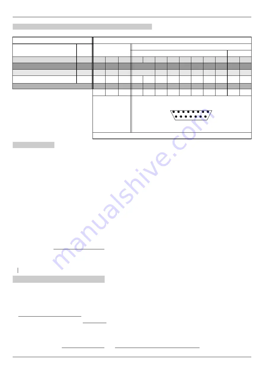
Example of connection of some motor models to the drive:
MOTOR MODEL
MOTOR SIDE CONNECTIONS
TYPE
SETT
HALL
MOTOR CABLE
TRANSDUCER CABLE
Tacho-generator 10V
PTC
Bosch SD-ISE
60°
1
3
2
10
4
5
9
11
3
2
1
Indramat MAC
120°
V1
W1
U1
11-2
4
10
12
7
8
9
Indramat MAC
120°
B
C
A
11-2
4
10
12
7
8
9
Signals:
U
V
W
ØV
DC- DC+ + 15V -15V SE1 SE2 SE3 PTC PTC
A
B
C
7
4
5
6
8
13
14
15
1
9
TERMINALS
CONNECTOR X14 (pin)
1
8
9
15
WELDING SIDE VIEW
DRIVE SIDE CONNECTIONS
5.5.4.4 Settings
Follow these points for proper commissioning of the transducer card:
1. Check that the X4 connector has no connection.
2. Attach the transducer connector to X14 or X14b depending on the type of transducer.
3. Provide service power to the drive and perform all standard settings (paragraph ”Calibration and adjustments“ on page 53
and paragraph ”Setting motor parameters“ on page 54).
4. Navigate the drive menu to the “Quick setup → Motor Parameters → Feedback Type” parameter. Use the keys to change set-
ting and select:
◦
Tacho D.C.
: To use a DC Tacho-generator with DC motor (connections to paragraph 5.5.4.1).
◦
Tacho Br.
: To use a brushless Tacho-generator with brushless motor (connections to paragraph 5.5.4.2).
◦
Tacho 10V
: To use a 10V Tacho-generator with brushless motor (connections to paragraph 5.5.4.3).
If it is impossible to select one of the above transducers, check if the card is compatible and if it has been recognised by mov-
ing to the “Diagnostic → Transduc Board → Transduc. Board for...." and verify that the words "TachoGen" are present. If
this does not occur, please contact the ALTER Technical Office for some verifications.
5. Scroll through the menu to the "Quick setup → Motor Parameters → Tachogenerator“ parameter. Set the voltage generated
by the tachometer dynamo when the motor runs at 1000 RPM, as reported on the plate or on the technical data of the trans-
ducer.
6. At this point, if you use a brushless motor, you can perform the autotune of the motor parameters as explained in paragraph
”Autotune for the synchronization of the transducer“ on page 54.
7. At the end of the autotune procedure, the parameters must be stored in order to complete the commissioning of the transducer
card.
NOTE:
If the “Feedback Fault” alarm appears using a d.c. motor, see the paragraph 6.4.13 on page 72.
5.5.5 Manual offset calibration
When the following transducer cards are used: 01/325 or 01/327, you can calibrate the offset to compensate for incremental sinusoidal
analog signals.
This offset, if present, causes problems in the speed signal that is wavy and during operation makes the motor vibrate or makes the ad -
justment unstable. To solve this problem, the drive automatically calculates the offset of the two incremental sinusoidal signals (sig-
nals on X14 pins 3,4,6,7), after manual activation of the function.
To manually start the offset calibration, you can follow these points:
1. The drive MUST be disabled (Led RUN off).
2. Move to the menu ”Diagnostic → Transduc. Board → Man Offset Calc”.
3.
Switch to “Edit Parameter” mode. So you have to press the "►" button once again, which shows a ”
“ in the bottom left
corner, press the key “▲” to enable the calibration cycle: the inscription becomes “ENABLED”.
4.
Spin the motor (at a speed above 50 RPM), then stop
turning the motor and let it
stop
for
inertia.
Alter Elettronica s.r.l.
61


