43
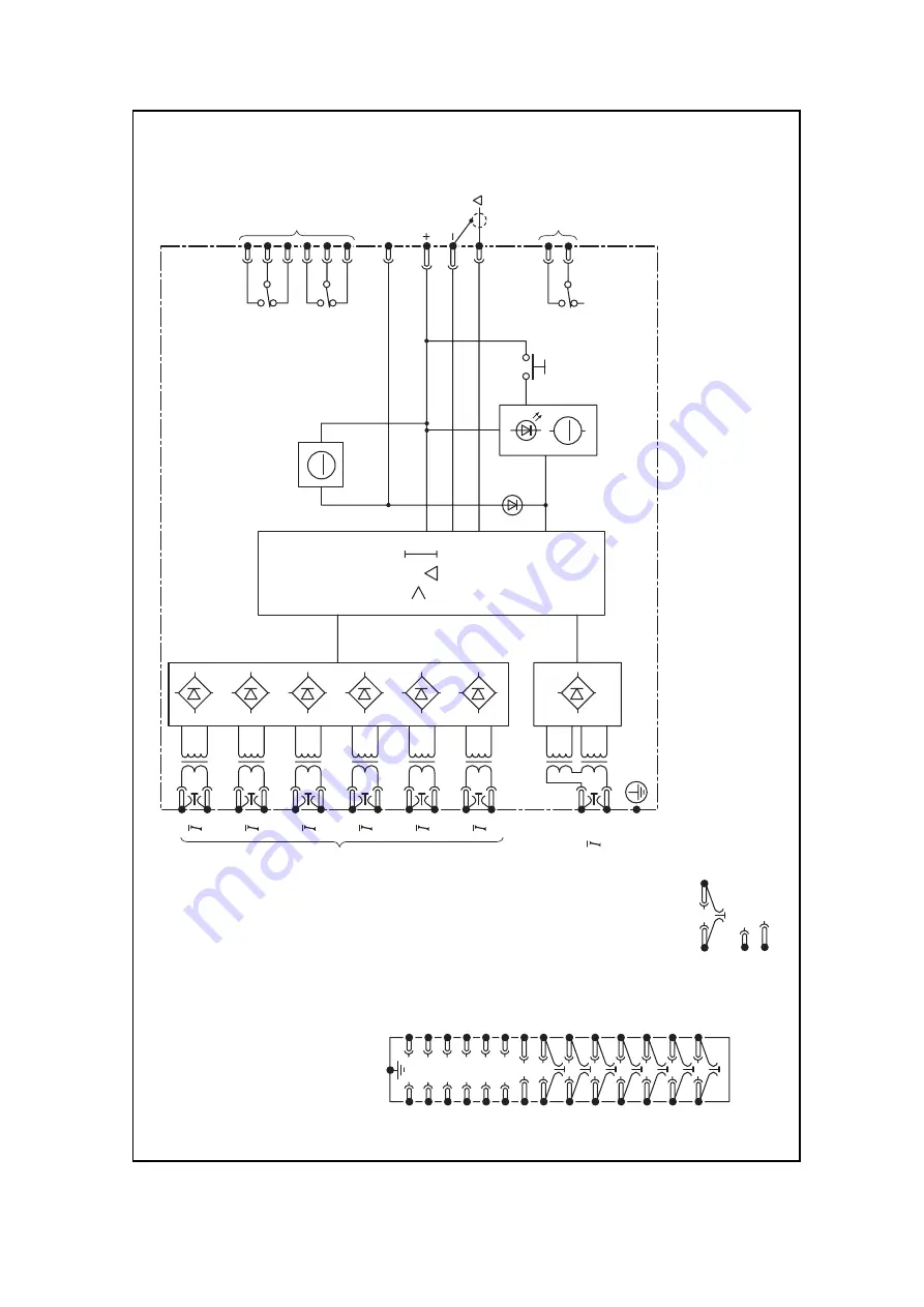
Figure 15 Block diagram: biased differential protection relay Type MBCH16 with six biased inputs
15
16
T8
17
18
T7
19
20
T6
21
22
T5
23
24
T4
25
26
T3
27
28
T1
T2
RL1
2
Output
circuits
RL2
1
1
3
5
RL1–1
2
4
6
RL1–2
10
13
14
12
9
11
RL2–1
12
34
56
78
91
0
11
12
13
14
15
16
17
18
19
20
21
22
23
24
25
26
27
28
Module ter
minal
block viewed
from rear
Case ear
th
Input circuits
Input circuits
Reset
Trip
other
phases
V
x
Trip
output
Alar
m
See following sheets
6
5
4
3
2
1
See following sheets
DIFF
2.
Te
rminal 12 on each phase assembly should
be interconnected by a screened lead GJ0153 001
with the screen connected to ter
minal 14.
Notes:
1.
(a)
CT shor
ting links make
before (b) and (c) disconnect.
(b)
Shor
t ter
minals break before (c).
(c)
Long ter
minals.
Bias
(see Note 2)


