Description and operation
Description of the interrupting chambers
L12--105EN/03
2/4
01--2011
© ALSTOM 2010. All rights reserved. Information contained in this document is indicative only. No representation or warranty is given or should be
relied on that it is complete or correct or will apply to any particular project. This will depend on the technical and commercial circumstances. It is
provided without liability and is subject to change without notice. Reproduction, use or disclosure to third parties, without express written authority, is
strictly prohibited.
GRID
Interrupting chamber
Quenching medium
The quenching medium is pressurized SF
6
gas or -- in particular instances --
pressurized SF
6
+CF
4
gas mixture.
Interrupting principle
The interrupting chamber is of thermal blasting type, using the energy from
the arc, with an auxiliary autopneumatic effect.
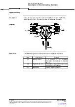
Diagram
4
2
1
Description
The interrupting chamber has been designed in such a way as to increase the
mechanical resistance of the working part and take advantage of the low wear
rate of the contacts subjected to the arc in SF
6
. The working part is enclosed
in a leak tight ceramic envelope, providing insulation between the
circuit--breaker input and output.
The chamber is made up of the following elements :
Mark
Component
Information
(1)
Envelope
Can have a long creepage
distance,
depending
on
the
pollution level.
(2)
Fixed contact
(4)
Moving contact
It is worked by the operating
mechanism and contains the
blasting device.


