background image


Airfield Lighting Systems UK Limited 

Aviation House, Russell Gardens, Wickford 

Essex SS11 8BF Tel +44 1702 547866 

[email protected]


www.alsukltd.co.uk


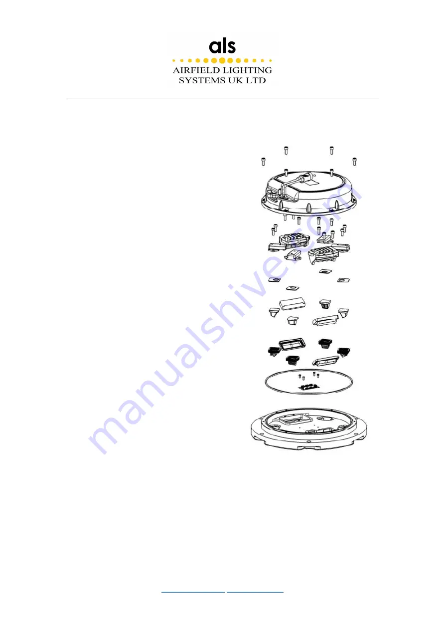
4.2.4 Replace the prism and its sealing gasket 

1. Place the light fixture upside down, remove the 
six  m5  ×  16  hexagon  screws,  and  separate  the 
upper cover from the bottom cover (if the upper 
cover  and  the  bottom  cover  are  adhered  too 
tightly, pry it open with the help of a large slotted 
screwdriver).   

2. Unplug the connector between the LED module 
and the electrical driver and separate the upper 
cover and the bottom cover.   

3. Remove the six M5 × 16 hexagon screws, and 
take  out  the  prism  pressing  plate  and  prism 
gasket. 

4.  Attach  the  prism  pressing  plate  and  prism 
gasket.  (Confirm  that  the  specifications  of  the 
prism and the replaced prism are consistent). 

5.  Install  the  prism  gasket  and  prism  pressing 
plate on the upper cover, and tighten with six m5 
× 16 hexagon socket screws.   

6.  Connect  the  connector  LED  module  to  the 
electrical  driver  in  the  bottom  cover.  Align  the 
bottom cover with the pin hole on the upper cover, 
and screw in the six m5 × 16 inner hexagon cap 
screw to fasten firmly. 

7. Perform water-tightness test. If air leaks out of 
the light fixture, locate the leaking point and open 
the  lamp  for  repair. After  rechecking,  assemble 
the light fixture and perform the water-tightness test again. 


Summary of Contents for RB/IN-RW(L)-C

Page 1: ...ing Systems UK Limited Aviation House Russell Gardens Wickford Essex SS11 8BF Tel 44 1702 547866 sales alsukltd co uk www alsukltd co uk 12 Inch LED Inset Runway Edge Light with Circular Guidance Inst...

Page 2: ...ribed in the manual may result in personal injury death or property and equipment damage Use this equipment only as described in the manual ALS cannot be held responsible for injuries or damages resul...

Page 3: ...al errors ALS reserves the right to revise this manual from time to time in the contents thereof without obligation of ALS to notify any person of such revision or change Details and values given in t...

Page 4: ...ce with standards 6 2 3 Features 6 2 4 Power and power factor 7 2 5 Dimensions and Weight 8 3 Installation 9 3 1 Tools and Material 9 3 2 Installation steps 9 3 3 Installation Bolt Torque 11 3 4Top Lo...

Page 5: ...observe a warning may result in personal injury death or equipment damage DANGER Risk of electrical shock or ARC FLASH Disconnect equipment from line voltage Failure to observe this warning may result...

Page 6: ...ble safety procedures required by your company industry standards and government or other regulatory agencies Install all electrical connections to local code Use only electrical wire of sufficient ga...

Page 7: ...a system that contains malfunctioning components If a component malfunctions turn the system OFF immediately Allow only qualified personnel to make repairs Repair or replace the malfunctioning compone...

Page 8: ...fixtures Light Fixture Ordering Code Optical Toe in Color Sketch Runway Edge Light width of runway is 45m RB IN WW L C Toe in 3 5 White White Runway Edge Light width of runway is 60m RB IN WW L C Toe...

Page 9: ...width of runway is 45m RB IN WY L C Toe in 3 5 White Yellow RunwayEdge Light width of runway is 60m RB IN WY L C Toe in 4 5 White Yellow Runway Edge Light width of runway is 45m RB IN YW L C Toe in 3...

Page 10: ...STANAG 3316 CAAC AC 137 CA 2015 01 CAAC AC 137 CA 2015 03 CAAC AC 137 CA 2017 03 2 3 Features Low protrusion of less than 6 3mm above ground level Modulized electrical driver and LED assembly for sim...

Page 11: ...onal beam Optional Fail Open System 2 4 Power and power factor Light Fixture Ordering Code Power Power factor Runway Edge Light RB IN WW L C 65VA 0 90 Runway Edge Light RB IN WR L C 54VA 0 90 Runway E...

Page 12: ...Airfield Lighting Systems UK Limited Aviation House Russell Gardens Wickford Essex SS11 8BF Tel 44 1702 547866 sales alsukltd co uk www alsukltd co uk 2 5 Dimensions and Weight Packing Data 6 11...

Page 13: ...allation holes on the pavement wiring base embedding and mounting of lights The installation of light fixture has a great influence on the function and service life of the lights Proper and adequate t...

Page 14: ...clean all contact surfaces of the light fixture and the base 2 Put the O ring gasket in the gasket track on the base 3 Connect the connector s of the light fixture to the base supply cable s Check tha...

Page 15: ...ll the M10 bolts with lock washers per lock washer manufacturer s guidelines See Section 2 for Top Lock installation guidelines Achieve a full final torque of 26 9 Nm Use GTP600 lubricants to 33 Nm wi...

Page 16: ...al pass on each bolt working clockwise from bolt 1 at 26 9 Nm Use GTP600 lubricant at 33 Nm torque 12 inch Inset Light 8 inch Inset Light WARNING The inset lights are designed to withstand a maximum t...

Page 17: ...and nut will cause serious damage to product installation and cause a variety of safety risks Ignoring these warnings may result in equipment damage or airport foreign objects CAUTION When a light fix...

Page 18: ...orkshop Maintenance The workshop maintenance includes the following Replacement of light fixtures Checking water tightness Replacement of a prism and its gasket Replacement of LED module CAUTION Be su...

Page 19: ...its base 1 Use a torque socket wrench to remove the M10 30 bolts spring washer and flat washer 2 Pry up the lighting fixture with the 8 inches lighting fixture pry bar 3 After the light fixture and b...

Page 20: ...nd the bottom cover 3 Remove the four M4 10 cross pan head screws and get out the LED light source assembly 4 Attach the new LED assembly on the prism pressing block in diagonal order with four m4 10...

Page 21: ...3 Remove the six M5 16 hexagon screws and take out the prism pressing plate and prism gasket 4 Attach the prism pressing plate and prism gasket Confirm that the specifications of the prism and the re...

Page 22: ...ure 1 If air leaks out continuously between bottom cover and upper cover or between prism and upper plate or between gas valve and bottom cover the light fixture is not watertight and must be repaired...

Page 23: ...ixtures List of components and spare articles No Name Order type Description 1 Upper cover UC 12 RBC33 Upper cover for inset runway edge lights 2 Circuit board CB C01 Only used for nset runway edge li...

Page 24: ...uk BC 12 II WW Used for RB IN WW L 2 plugs BC 12 II CW Used for RB IN WR L RB IN RW L RB IN WY L or RB IN YW L 2 plugs BC 12 II CC Used for RB IN YR L or RB IN RY L 2 plugs 1 Upper cover 2 Circuit bo...

Reviews: