background image

9

>100

705 Dia.

>300

>100

716

1002

325

169

E

50

50

51

35

A

B

C

D

Alpha SolarSmart 150 - General Information

3.4

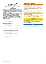
SOLAR CYLINDER INFORMATION - Fig. 5

Positioning

The Solar cylinder must be installed on a flat horizontal surface which is capable of supporting the weight of the cylinder
when full (190 kg).

The cylinder may be installed in any room or internal space, although particular attention is drawn to the requirements of
the current IEE Wiring (BS7671) Regulations, and in Scotland, the electrical provisions of the Building Regulations
applicable in Scotland, with respect to the installation of the cylinder in a room or internal space containing a bath or
shower. When the cylinder is installed in a room containing a bath or shower, it must not be possible for a person using
the bath or shower to touch any electrical switch or cylinder control utilising mains electricity.

The bottom of the Solar cylinder must be located within 6 metres of the top of the drain back unit.

Dimensions

The dimensions of the cylinder and clearances required for servicing are shown in Fig. 5.

Water connections

Fig. 5

The connections at the bottom of the cylinder are shown in Fig. 5.

Note: Use compression fittings only on the cylinder connections and copper pipe between the cylinder and drain back
unit. We also recomend a minimum of 1 metre of copper pipe from the cylinder for the water inlet and outlet connections.

Cylinder Connections

Water outlet to boiler

15 mm

Cold water inlet

15 mm

Return from DBU

15 mm

Flow from cylinder to DBU 15 mm

Cylinder sensor

For latest prices and delivery to your door visit MyTub Ltd - www.mytub.co.uk - [email protected] 0844 556 1818   

Summary of Contents for SolarSmart 150

Page 1: ...Sevenoaks Kent TN157RS For Technical help or for Service call ALPHAHELPLINETel 08448718764 website www alpha innovation co uk Leave these instructions with the User Building Regulations Approved Cert...

Page 2: ...arried using the lifting forks when on the original wooden pallet base IMPORTANT This System has been approved to the Building Regulations for unvented hot water storage systems and the Local Authorit...

Page 3: ...ss 44 Nett 8 95 5 4 Aluminium Pressing 50 0 037 Aluminium Black Powder Coated 10 k 12 mm 15 mm 5 4 GJ yr 1500 kWh yr 2 panels 74 3 629 0 9 80 l h 9 kPa Same as Supporting Roof Structure Wind Speed 27...

Page 4: ...between the solar collectors drain back unit and cylinder MUST be copper with compression fittings on the collector to drain back circuit and compression fittings onto all cylinder connections Supply...

Page 5: ...10 Control PCB 11 Overheat thermostat 12 Drain point for cylinder 13 Unvented kit 14 Expansion relief valve 15 Expansion vessel 16 Non return valve 17 Pressure reducing valve with filter 18 Tundish To...

Page 6: ...prevent high temperatures at the hot water taps it is recommended that a thermostatically controlled mixing valve is fitted after the boiler 3 3 UNVENTED HOT WATER STORAGE SYSTEM To comply with the B...

Page 7: ...hermostat sensor Solar collectors maximum of 4 Drain back unit Drain back unit pump Cylinder pump Heat exchanger Drain point Thermostatically controlled mixing valve Cold water supply Filter Pressure...

Page 8: ...elief valve is 9 m Subtract the resistance for four 22 mm elbows of 0 8 m each 3 2 m Therefore the maximum permitted length equates to 9 3 2 5 8 m 5 8 m is less than the actual length of 7 m therefore...

Page 9: ...it must not be possible for a person using the bath or shower to touch any electrical switch or cylinder control utilising mains electricity The bottom of the Solar cylinder must be located within 6...

Page 10: ...ar collectors 2 The tubing from the solar collectors must always slope down towards the drain back unit at least 40 mm per metre 3 There must not be any part of the tubing that will allow water to col...

Page 11: ...weatherproof Full details of this type of installation are provided in the instructions supplied with the kit b Positioning of a landscape collector onto a flat roof Using the Alpha Flat Roof Kit Part...

Page 12: ...ls Part No 6 4000760 Left hand portrait kit Part No 6 4000780 Right hand portrait kit Part No 6 4000770 Centre portrait kit Part No 6 4000660 Left hand landscape kit Part No 6 4000680 Right hand lands...

Page 13: ...secured in position using the fixings supplied To fit the DBU on wall 1 With the help of Fig 6 decide upon the position of the unit taking into account the clearances required around the unit 2 Remov...

Page 14: ...alve is mounted correctly i e the arrow marking on the valve body is pointing in the direction of flow 5 Connect the mains water supply to the pressure reducing valve and thoroughly flush out the wate...

Page 15: ...late the filling loop after filling the central heating system 23 20 M Brass plug L J H K G I C B F D E A 65 70 45 70 58 95 37 N M Filling loop N 23 20 C B F D E A 65 70 45 70 58 95 37 G I L J H K M N...

Page 16: ...Ensure that the cable is secured in the cable clamp 5 in Fig 18 3 Connect the Collector Sensor The sensor has a 7 metre cable Plug the white sensor cable into the blue connector sensor cable and route...

Page 17: ...ose the ball valve on the manifold to prevent water from draining out of the cylinder Fig 20 5 Remove the relief valve assembly by undoing the socket head capscrew using a 6mm Allen key Fig 20 6 Caref...

Page 18: ...the system can be turned on and off using the button When the button is held in for 5 seconds the diagnostic mode will be entered Refer to Section 7 If the button is not touched for 5 seconds the last...

Page 19: ...ulated around the collector When the heated water enters the drain back unit heat is transfer into the stored water via a heat exchanger coil Stored domestic hot water is pumped from the bottom of the...

Page 20: ...m of the cylinder through the drain back unit heat exchanger and warm water back to the centre of the cylinder Collector water circuit The drain back unit pump See Fig 22 is controlled by the PCB The...

Page 21: ...he side of the cylinder housing Always carry out electrical system checks i e earth continuity resistance to earth short circuit and polarity with a suitable meter after any electrical work has been c...

Page 22: ...BU as it reaches very high temperatures and can emit steam from connections when being removed Isolate the electrical supply before removing the casing Undo the two screws at the top and two screws at...

Page 23: ...r it to stop see fig 20 Drain the water from the cylinder as described in Section 8 1 Undo the four pipe connections on the heat exchanger and the two support bracket nuts and remove the heat exchange...

Page 24: ...n in the collector Check water level in drain back unit Check overheat thermostat manually reset if required Check the difference in height between the drain back unit pump and the upper most side of...

Page 25: ...reducing valve situated Has the expansion vessel or internal air space been checked Yes No FOR ALL INSTALLATIONS CONFIRM THE FOLLOWING The hot water system complies with current Building Regulations...

Page 26: ...nbackrighttailconnection Expansionreliefvalve Collectortemperaturesensorlead Plugandlead overheatthermostst Collector hoses fittings DBU to collector HT pipe insulation pack DBU to collector Clips cyl...

Page 27: ...ts Date of Installation Name of Installer Address Postcode Telephone No Cylinder Serial Number see data label on top of cylinder underneath the cover or bottom of cylinder refer to Fig 5a for position...

Page 28: ...specification at any time in the interest of product improvement Alpha Therm Limited 2010 Alpha Therm Limited NepicarHouse LondonRoad WrothamHeath Sevenoaks Kent TN15 7RS Tel 0844 8718764 email info a...

Reviews: