ADM-PCIE-KU3 User Manual
3.1.2 LEDs
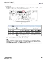
There are 7 LEDs on the ADM-PCIE-KU3, 3 of which are general purpose and whose meaning can be defined
by the user. The other four have fixed functions described below:
DONE
D1
D3
D4
D5
D6
D7
D2
SYS_OK
CLOCK_LOS
SYS_Fault
USR_LED0
USR_LED1
USR_LED2
Figure 5 : LEDs
Comp.
Ref.
Function
ON State
OFF State
D1
DONE
FPGA is configured
FPGA is not configured
D2
CLOCK_LOS
Clocks not operating normally
Clocks operating normally
D3
USR_LED0
User defined '0' pin AE12
User defined '1' pin AE12
D4
USR_LED1
User defined '0' pin AF12
User defined '1' pin AF12
D5
USR_LED2
User defined '0' pin AD11
User defined '1' pin AD11
D6
SYS_Fault
Temperature or voltage warning/fault
System monitor OK
D7
SYS_OK
Temperature and voltage within tolerance
Temperature or voltage out of tolerance
Table 4 : LED Details
Use IO Standard "LVCMOS33" when driving the user LED pins.
Page 6
Functional Description
ad-ug-1284_v1_13.pdf


