background image

Note: 

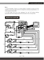
WIRING DIAGRAM

Electric Heat Drying System

12

Main Control Board

Relay 2

Relay 1

Relay 4

Relay 3

White

White

White

Black

Black

Ndicator Light 1#

Overload Protection 
Switch 1#

White

Overload Protection Switch 3#

Black

Black

Red

Red

Red

Black

Black

Temperature Switch Thermal 
Protector 2#

Ptc Resistance Wire 2#
1500w

Ndicator Light 2#

Green

White

Ptc Resistance Wire 2#
1500w

Temperature Switch Thermal 
Protector 4#

Ndicator Light 4#

White

Overload Protection Switch 4#

Overload Protection Switch 2#

Ptc Resistance Wire 3#
1500w

Temperature Switch Thermal 
Protector 3#

Ndicator Light 3#

Ptc Resistance 
Wire 1#


1500w

Temperature Switch 
Thermal Protector 1#

Starting Capacitor

Centrifugal 
lmpeller 
Group

COM

NO

COM

NO

COM

NO

COM

NO

Monitor

Air Inlet Temperature Probe

T

Power


1

#

Power


3

#

Power


4

#

Power


2

#

N

N

L

L

Summary of Contents for MaxFireDry 200

Page 1: ...MaxFireDry 200 Portable Heater OWNER S MANUAL Electric Heat Drying System Specifications subject to change without notice AlorAir Solutions INC ...

Page 2: ......

Page 3: ...f electric shock do not use overload sockets or extension cables Check the power rating before use In order to provide continuous protection against the risk of electric shock you can only connect sockets with grounding Make sure you have read and understood this manual before operating the machine Check whether there is any damage on the outside of the machine before operation If there is any dam...

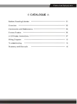
Page 4: ... Electric Heat Drying System 01 02 04 06 07 12 13 14 Matters Needing Attention Overview Accessories and Maintenance Service Section LCD Display Instructions Wiring Diagram Troubleshooting Warranty and After sale ...

Page 5: ...MATTERS NEEDING ATTENTION Electric Heat Drying System 01 ...

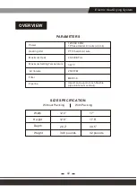
Page 6: ...Maximum Heat 20 000 BTUs Maximum Setting Temperature Air Volume 250 CFM Filter MERV 8 Pipeline Import and export 8 inch flexible pipe aluminum conduit Width 12 6 17 Height 12 6 17 8 Depth 26 2 30 5 Weight 34 6 pounds 42 pounds SIZE SPECIFICATION Without Packing With Packing Electric Heat Drying System 02 ...

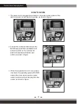
Page 7: ...data cable to the EXTERNAL CONTROL GONNECTOR socket to switch on the controller for external temperature detection and control as shown in figure When the equipment is not in use please shut down the operating system POWER button first then disconnect the rocker switch and then pull out the plug from the socket as shown in figure Electric Heat Drying System 03 1 2 3 ...

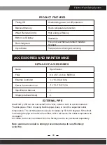
Page 8: ... 9 x 8 7 x 0 6 in MERV 8 1 2 EXTERNAL PIPE MaxFireDry 200 can be connected to the inlet outlet or both to accommodate 8 flexible pipes When choosing flexible pipes keep in mind the expected outlet temperature The air temperature usually increases by 50 to 80 degrees Fahrenheit Increasing the pipe will reduce the airflow which will cause the outlet temperature to rise again Air intake ducts can be ...

Page 9: ...ll make the heating element work again It must be checked regularly Replacement filters can be ordered from the factory or purchased locally if any Warning do not operate this machine without a filter or using an inefficient filter Do not operate the machine without the upper cover installed The presence of high pressure may cause the heater to burn out Warning repairing MaxFireDry 200 alone can c...

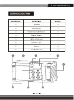
Page 10: ...umber Specification Foot Pad Main Switch External Controller Socket Display Screen MERV 8 Filter Net Indicator Light Socket Overload Switch Number 1 3 2 4 5 6 7 8 8 1 1 1 1 1 4 3 1 2 3 4 5 6 7 8 Electric Heat Drying System 06 ...

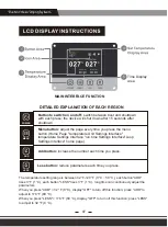
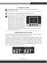
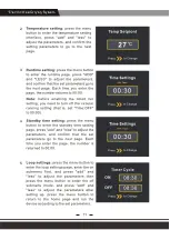
Page 11: ...Add button increase the number each time you press Less button reduce parameters each time you press MAIN INTERFACE FUNCTION The temperature setting range is between 32 F 120 F 0 C 50 C each button ADD rises 3 F 1 C each button LESS rises 3 F 1 C long time can continuously adjust the parameters When you press ADD 32 F 0 C display OFF to turn off this function press ADD to adjust to 176 F 80 C When...

Page 12: ... up and the heating wire closes the icon to hide Fan start fan icon lights up and rotates fan stop icon is hidden The machine has been locked and long press MENU ADD to exit th enother keys can be operated MENU LESS ADD Electric Heat Drying System 08 ...

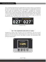
Page 13: ...Temp Setpiont Press to Change 27 C MENU LESS ADD Electric Heat Drying System 09 ...

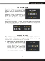
Page 14: ...re set the time of timing off is consumed to 0 and then the clock and the device are activated and turned on at the same time until the set time is finished and then enter the cycle GENERAL SETTING 1 Electric Heat Drying System 10 ...

Page 15: ...2 3 4 5 Electric Heat Drying System ...

Page 16: ...tance Wire 2 1500w Ndicator Light 2 Green White Ptc Resistance Wire 2 1500w Temperature Switch Thermal Protector 4 Ndicator Light 4 White Overload Protection Switch 4 Overload Protection Switch 2 Ptc Resistance Wire 3 1500w Temperature Switch Thermal Protector 3 Ndicator Light 3 Ptc Resistance Wire 1 1500w Temperature Switch Thermal Protector 1 Starting Capacitor Centrifugal lmpeller Group COM NO ...

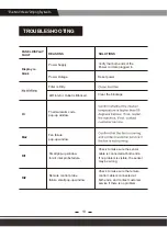
Page 17: ...connected at both ends and contact customer service if there is no problem Remote control probe failure small pop up window Ma2 Rt1 Power Outage Reset power Thermal alarm code pop up window Small pop up window for air inlet probe failure Check to make sure the sensor cable is connected at both ends If no problem is visible the sensor may be wrong Rt2 Clear the blockage AIR Inlet or Outlet is Block...

Page 18: ...osts for units repair 3 Customers can pick up the unit after repair at their own expense for shipping Units will have a rigorous testing before sending it back to customers 4 lf the unit can no longer be fixed and it is in the warranty period and determined to be valid claim we will ship the customer a new unit with in the same year warranty from the date of replacement 5 After parts are repaired ...

Page 19: ...ch or alleged breach of warranty by seller Any dishonesty or fraud in connection with AlorAir warranty thoroughly voids all warranty policies AlorAir expressly reserves the right to pursue legal action in the event of dishonesty fraud or attempted fraud DAMAGE DUE TO THE FOLLOWING IS NOT COVERED UNDER WARRANTY POOL SPA TUB APPLICATIONS MISUSE ABUSE OR TAMPERING WHETHER INTENTIONAL OR ACCIDENTAL IM...

Page 20: ......

Reviews: