background image

ww
w.v

en

t

�l

at

on

-a

l

no

r.c

o.

uk

12

A

LNOR

®


vent

lat

on systems

s a legally protected trademark and techn

cal patent. All r

ghts reserved.

User’s manual of recovery vent

lators HRU-M

n

stA

r-W-450

Selection of electrical cable cross-section

U

n�t M

o

d

e

l

Un�t Power Input

(kW)

HRU-M

n

stA

r-W-450

230

0.166

0.5

0.5

1.5

Un�t Voltage

(V)

Current

(A)

Fuse

(A)

Cable Cross-Sect�on(mm²)

for 50M and PF=0.8

current

cable

 > I 

fuse


> I 

current

cable

 > I 

fuse

 > I 

current

cable

 = 12A

S3  = 0.5 mm²

Cable cross-section S = Max (S1, S2, 

S

3, 1.5 mm²)

S = 

Max (0.5, 0.5, 0.5, 1.5)

S = 

1.5 mm²

cable

 > 0.5A > 0.09A

“I 

fuse

”which will be higher than “I 

current

”, is selected.

S2  > 

0.09 mm² > 0.5 mm²

S2 = 

0.5 mm²

Cable Cross-Section  S=Max (S1, S2, S3, 1.5mm²)

%e

S

0.09 mm²

S

,

current

cable

%e=%3

%

e = 

%3

S1 = 

0.5 mm²

1

1

P

I

U

S

k

L

%e

:
:
:
:
:
:
:

Power

Current
Voltage

Conductor cross section
Conductor coefficient

Conductor length
The voltage drop

2

2

3

3

>

P

166 W

100.P.L

100.166.50

100.P.L

U.CosQ

230.0,8

k.S.U²

56.3.230²

k.%e.U²

=

=

=

=

=

=

=

P

U

PF

L

%e

k

:

:

:

:

:

:

0,169 kW

230V

CosQ 

: 0,8

50m

%3

56m / 

Cable Cross-Sect�on Formulas

Example of Cable Cross-Sect�on Calculat�on

The cable will be used, is selected from the cable cross-section table so 

that  the  equivalent  ampere  value  in  the  table  should  be  high

er than 

calculated “I 

current

” value.

The cable will be used, is selected from the cable cross-section table so 

that  the  equivalent  ampere  value  in  the  table  should  be  higher  than 

selected “I 

fuse

” value.

current

0.9 A

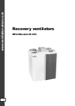
Summary of Contents for HRU-MinistAir-W-450

Page 1: ...www vent lat on alnor co uk Recovery vent lators HRU M n stA r W 450 1...

Page 2: ...ery vent lators HRU M n stA r W 450 Table of contenst SafetyInformat ons 3 Components 4 Techn calData 5 PerformanceCurve 6 SoundCurve 6 W r ng D agram 7 Un t D mens ons 8 Serv ceSpace 8 Installat on 8...

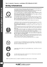
Page 3: ...heater etc Select an adequately sturdy pos t on for nstall ng the product and nstall t properly and securely Use the des gnated electr cal w res for the term nal board connect ons and connect the w re...

Page 4: ...450 Components HRU M n stA r W 450 un ts are des gned for recover ng part of the energy of the exhausted a r n a vent lat on system The recovered energy s d rectly transferred to the suppl ed fresh a...

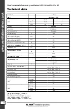
Page 5: ...nce flow rate 0 072 Reference pressure d fference Pa 50 SPI 2 W m h 0 259 Control factor and typology 1 Manual Declared leakage rates 0 3 Internal 0 4 External M x ng rate 0 Pos t on and descr pt on o...

Page 6: ...W 450 Performance curve Sound curve External Pressure Pa Air Volume m3 h 100 200 300 0 50 100 150 200 250 300 350 400 450 500 400 450 500 350 250 150 Octave Sound Pressure Level dB Overall A Scale Cen...

Page 7: ...LNOR vent lat on systems s a legally protected trademark and techn cal patent All r ghts reserved User s manual of recovery vent lators HRU M n stA r W 450 W r ng d agram www vent lat on alnor co uk 7...

Page 8: ...very vent lators HRU M n stA r W 450 Un t d mens ons 610 V ew from top V ew from front V ew from front All measurement values are mm A clear space of 600 mm must be prov ded n front of the un t for se...

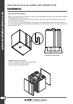
Page 9: ...not be less than the d ameter of the dra nage outlet connect on Not less than a d ameter of 20 mm 2 A un on or p pe coupl ng should be f tted at the p pe connect ons to perm t easy d sconnect on to cl...

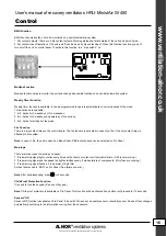
Page 10: ...t ngs Note By pass s nstalled as a standard Connect on of Power Supply 1 Power supply 230V 50Hz 1 Phs power connect on L N Ground 2 Control cable 5m Length of control cable s 5m Please cabl ng th s co...

Page 11: ...brackets are f tted together f rmly Be sure that condensat on dra n s connected properly For level ng the un t use the screws wh ch are located at the bottom of the back surface of un t Floor Mount ng...

Page 12: ...is selected S2 0 09 mm 0 5 mm S2 0 5 mm Cable Cross Section S Max S1 S2 S3 1 5mm e S 0 09 mm S I current I cable e 3 e 3 S1 0 5 mm 1 1 P I U S k L e Power Current Voltage Conductor cross section Cond...

Page 13: ...an cally W th th s method when f lter needs to be changed control board g ves an alert Electr c Heater Control Funct on Electr c heater s controlled up to 2 steps automat cally accord ng to the set te...

Page 14: ...lter change After f lter clean ng s done f lter sett ng t me can be reset by press ng s multaneously and Hold the buttons dur ng reset t me that appears on screen When countdown s over press Note Defa...

Page 15: ...ure and works due to set and return a r temperature It can control 230V on off valve connected to water co l Note To act vate th s funct on follow ng must be appl ed Turn electr c heater funct on on T...

Page 16: ...Only fans are runn ng 3 If red warn ng s gnal flashes t s an alarm of d rty f lter Screen fa lure code s ERR on Pro Panel See fa lure code l st Note After troubleshoot ng press for 3 seconds Ch ld Pr...

Page 17: ...v ous screen 3 Press to change any value on screen Press to ncrease ex st ng value 1 Press to decrease ex st ng value 1 6 Ch ld Lock To act vate th s funct on press and for 3 seconds When ch ld proof...

Page 18: ...Ma n Screen T mer Company Introduct on Screen Br ghtness and Contrast Sett ng Panel Screen 1 Sreen Symbols Ma n Screen Standard mode S ngle fan mode only exhaust fan s runn ng Supply fan Fan s off Fan...

Page 19: ...emperature There s no heater Heater s off There s no by pass By pass s off By pass s on Heater s on at f rst stage Heater s on at f rst and second stage There s water co l It s off Cool ng co l s on H...

Page 20: ...me of un t Shut down t me of un t T me hh mm ss Date yy mm dd Company logo and nternet address Pro panel software vers on Screen br ghtness value Screen contrast value TIMER s on 5 weekdays TIMER s on...

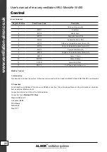
Page 21: ...RR 8 Supply a r temperature sensor fa lure SA 9 ERR 9 Sensor 1 fa lure 10 ERR 10 Sensor 2 fa lure 12 FILTER Alarm of d rty f lter 15 ERR 15 Pro Panel commun cat on error Error Code L st Modbus Connect...

Page 22: ...2 and 06 reg ster wr t ng Table 3 3 In the example below Table 3 2 master wants to know the 16 b t data on 2nd reg ster Correspond ng response value of control board s shown on the table below In the...

Page 23: ...80 TerP 15 Sensor 1 nput 0 01 r 16 Sensor 2 nput 0 01 r 25 Alarm code 1 r Fa lure Code 36 Rotor status 1 r 0 1 0 Off 1 On 37 By pass status 1 r 0 1 0 Off 1 On 38 Pre heater status 1 r 0 1 0 Off 1 On 3...

Page 24: ...nd techn cal patent All r ghts reserved User s manual of recovery vent lators HRU M n stA r W 450 Control Pro Panel D mens ons Pro Panel Installat on 106 mm 82 mm 24 mm www vent lat on alnor co uk 24...

Page 25: ...sehold vacuum cleaner Ma ntenance TURN OFF all the power sw tches before the ma ntenance s performed Do not operate the system w thout the a r f lter to protect the components of the un t aga nst be n...

Page 26: ...www vent lat on alnor co uk 26 ALNOR vent lat on systems s a legally protected trademark and techn cal patent All r ghts reserved User s manual of recovery vent lators HRU M n stA r W 450 Energy Label...

Reviews: