ALNOR
®
ELECTRONIC
BALANCING TOOL
MODELS EBT730/EBT731
OWNER’S MANUAL
P/N 6005725, REV D
OCTOBER 2014
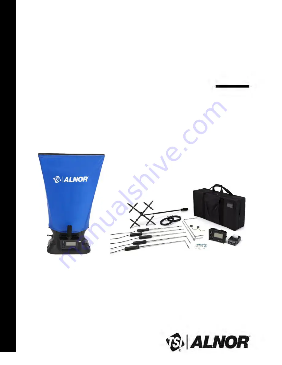
Model EBT731 Balometer
®
Model EBT730 Micromanometer
Air Balancing Instrument
(shown with standard and optional accessories)
www.
GlobalTestSupply
.com
Find Quality Products Online at:
[email protected]


