6
GEARBOX REASSEMBLY
-
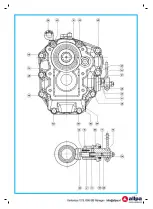
Output shaft unit assembly: orderly assemble, starting from the end opposite the output flange, spacer ref. 6, bush ref.
29, cage ref. 37, gear ref. 24, spacer ref. 7, bearing cone ref. 53, nut ref. 18 (torque wrench setting 155 Nm). Tighten the
stop nut in the appropriate place on the shaft. Insert clutch unit ref. 21 and moving toward the output flange end, assemble,
in sequence, the following parts: ref. 6, 29, 37, 23, 7, 53.
-
Intermediate shaft unit assembly: upon positioning stop ring ref. 32 and distance ring ref. 4 assemble the cups of the
two bearings ref. 52 on gear ref. 22. Assemble the bearing cone on shaft ref. 10 making it close on the shoulder. Insert
the gear on the shaft and assemble the last cone. Assemble lock washer ref. 38 and ring nut ref. 27 fastening the ring
nut very tightly in order to move bearings ref. 52 to the correct position; loosen the ring nut until the gear can rotate
smoothly, which corresponds to an adjustment leaving zero play of the bearing, and lock the ring nut into place by means
of the lock washer.
- Input shaft unit assembly: the gears are enbloc with the shaft; therefore it is necessary only to assemble the cones of
Disassembly and assembly of the gearbox or of its parts is to be made by specialized technicians only.
!
The gearbox is supplied without oil. Before the first start-up it must be filled up to the maximum level marked
on the dipstick. Use ATF oil.
Before to start the engine make sure that the gearbox is in neutral position.
The gearbox should only be shifted with the engine at idle speed so as to avoid that the gearbox or the
coupling may be demaged.
Disassembly and assembly of the gearbox or of its parts is to be made by specialized technicians only.
!
!
!
!
control cable. If the problem persists, it is necessary to disassemble the reverse-gear unit in order to check the status
of clutch ref. 21. If the clutch shows signs of wear or burns on its cone-shaped surfaces or on the groove, it must be
replaced. The cone-shaped surface on gears ref. 23 and 24 must also be checked; such surface must show no marks
of burning or seizure end no material deposits coming from the clutch cone otherwise the gears must be replaced. In
the case the clutch-unit alone is replaced, it is not necessary to disassemble adjusting shims ref. 5 and, therefore, bea-
rings need not to be adjusted during assembly.
GEARBOX DISASSEMBLY
In order to completely disassemble the reverse-gear unit, operate as follows:
- Remove the reverse-gear control unit by unscrewing M8 two nuts ref. 54 and extracting the whole unit (control lever ref.
16, cover ref. 2, shaft ref. 9, guide shoe ref. 20, screw ref. 28, nut ref. 56) carefully avoiding to drop guide shoe ref. 20 into
the reverse-gear unit as it has no axial lock.
- Remove output flange ref. 25 from the reverse-gear unit by unscrewing nut ref. 17 and by extracting the flange from the
shaft spline.
- Loosen fastening screws ref. 48, 49, 50 located between the box and the cover and, while holding the reverse-gear unit
in a vertical position, gently, beat the head of output shaft ref. 11 with a copper hammer in order to separate the box from
the cover.
- While the reverse-gear unit is open, remove input shaft ref. 12 together with bearing cones ref. 53 and the whole output
shaft. Loosen screw ref. 55 which fastens the intermediate shaft to the reverse-gear cover and remove the whole inter-
mediate shaft.
- In order to disassemble the clutch cone from the output shaft, extract all parts according to the following sequence: bea-
ring ref. 53 located on the flange side, spacer ref. 7, gear ref. 23, pin housing cage ref. 37, bush ref. 29 spacer ref. 6 and
clutch cone ref. 21.
- In order to complete the disassembly of the output shaft remove nut ref. 18 and extract, in the following order, bearing
ref. 53, spacer ref. 7, gear ref. 24, pin housing cage ref. 37, bush ref. 29 and spacer ref. 6.
- Spacers ref. 5 are located between cover ref. 3 and bearing ref. 53; therefore, in order to remove them it is necessary to
remove the cups of the taper roller bearings from their seats.
- Disassembly of intermediate gear ref. 22: straighten lock washer ref. 38 and unscrew ring nut ref. 27, extract gear ref. 22
towards the splined side of shaft ref. 10. Together with the gear also one of bearings ref. 52, distance ring ref. 4 and
stop ring ref. 32 and the cup of the other bearing ref. 52 will come out.
Disassembly and assembly of the gearbox or of its parts is to be made by specialized technicians only.
!


