POEGEM12T2SFP User Manual
9
Alloy Computer Products Pty Ltd Copyright ©2006
2. Installation
2.1. Starting the POEGEM12T2SFP SNMP Managed POE Switches
This section provides a quick start guide for:
•
Hardware and Cable Installation
•
Management Station Installation
•
Software booting and configuration
2.1.1. Hardware and Cable Installation
Please Note:
⇒
Wear a grounding strap to avoid damaging the switch with an electrostatic discharge
⇒
Be sure that the power switch is in the ‘OFF’ position before you insert the power cord
•
Installing Optional SFP
Mini-GBIC Modules
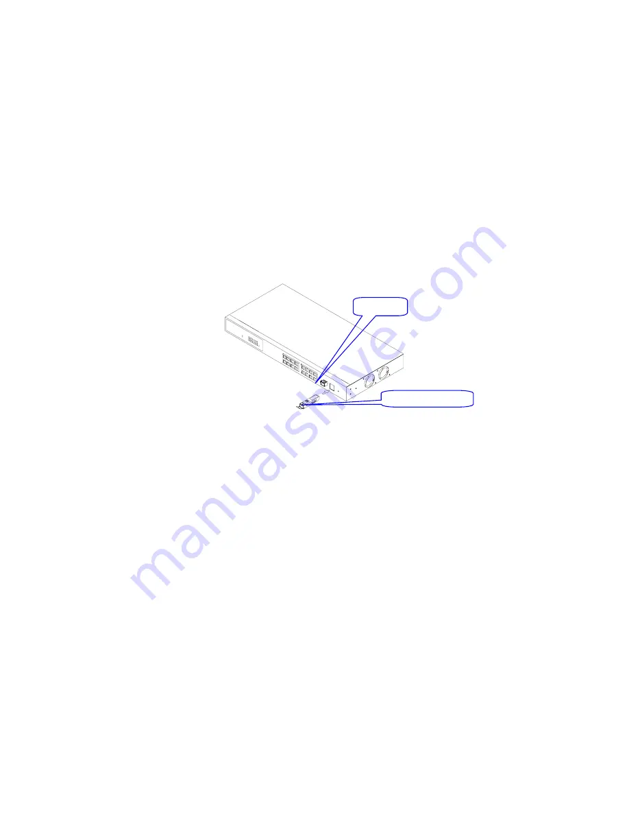
• Connecting the SFP Mini-GBIC Module to the Chassis:
The optional SFP Mini-GBIC modules are hot-swappable, so you can plug or unplug them while
the power is applied to the switch.
1. Verify that the mini-GBIC module is compatible with the SFP port on the switch (for example,
some switch manufacturer’s design their mini-GBIC modules to be operable only in their
branded devices).
2. Verify that the type of mini-GBIC you have selected for use will be compatible with the
type of fibre optic cable that is to be used.
3. Verify that the type of mini-GBIC you have selected for use will be compatible with the
fibre optic transceiver at the other end of the link (e.g. – compatible wavelength and
standard).
4. Slide the module along the slot and ensure that the module is properly seated against the
SFP slot socket/connector.
5. Install the media cable for network connection.
6. Repeat the above steps, as needed, for each module to be installed into the switch.
Fig.
2-1: Installation of optional
SFP
mini-GBIC
SFP port
Mini-GBIC module


