background image

21

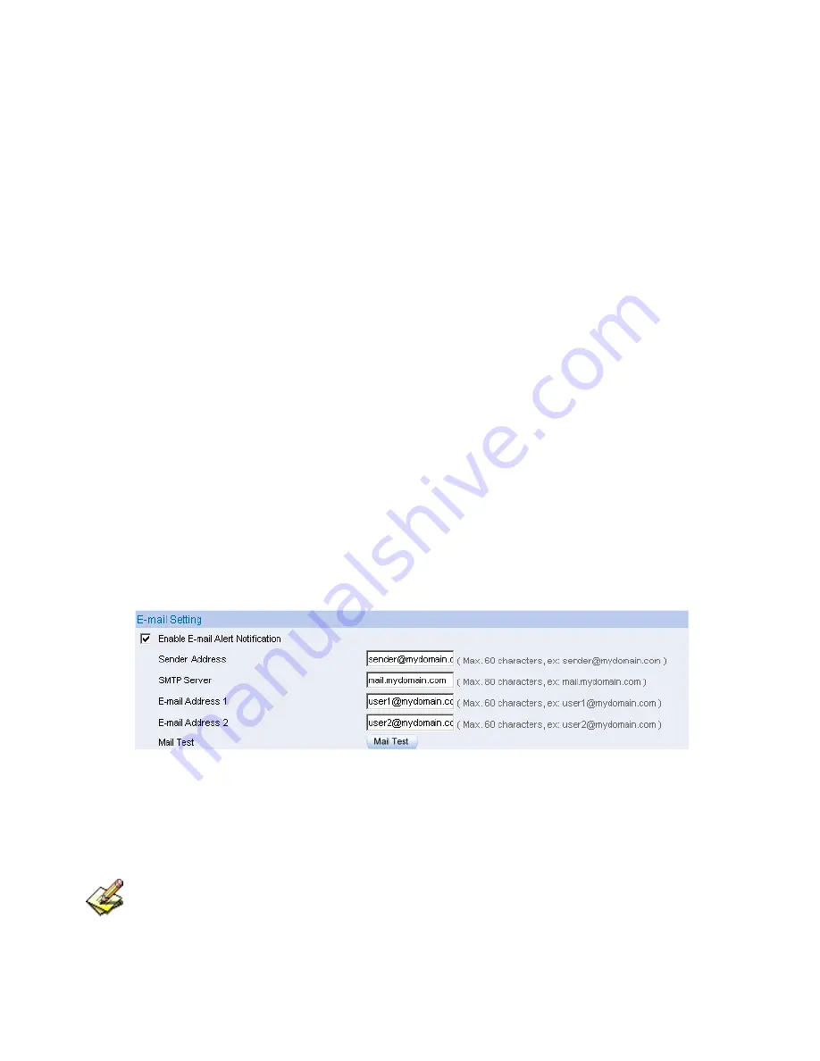
Enabling E-mail Alert Notification 

STEP 1

Select

 Enable E-mail Alert Notification

 under E-Mail Settings. 


STEP 2

Sender Address:

 Enter the Sender Address. (Required by some 

ISPs.) 


STEP 3

SMTP Server IP:

 Enter SMTP server’s IP address. 


STEP 4

E-Mail Address 1:

 Enter the e-mail address of the first user to be 

notified. 


STEP 5

E-Mail Address 2:

 Enter the e-mail address of the second user to be 

notified. (Optional) 


STEP 6

Click

 OK 

on the bottom-right of the screen to enable E-mail Alert 

Notification. (Figure2-5) 


Figure2-5 Enable E-mail Alert Notification 


Click on 

Mail Test

 to test if E-mail Address 1 and E-mail Address 2 can receive the 

Alert Notification correctly. 

Summary of Contents for ALL7008

Page 1: ...ALL7008 User s Manual...

Page 2: ...mitted IPs 9 Logout 10 Software Update 11 Chapter 2 Configure 13 Setting 18 Date Time 23 Multiple Subnet 24 Route Table 27 DHCP 36 DDNS 38 Host Table 40 Language 41 Interface Chapter 3 Interface 43 LA...

Page 3: ...Example 87 Chapter 8 Authentication 91 Auth User 97 Auth User Group 101 RADIUS 105 POP3 Server 126 Chapter 9 Content Blocking 129 URL 133 Script 136 P2P 138 IM 140 Download 142 Chapter10 Virtual Serve...

Page 4: ...365 Example 371 Anti Attack Chapter16 Alert Setting 381 Internal Alert 386 Chapter17 Atack Alarm 391 Internal Alarm 393 External Alarm 394 Monitor Chapter18 LOG 397 Traffic Log 399 Event Log 404 Conn...

Page 5: ...4 Chapter21 Status 423 Interface 424 Authentication 426 ARP Table 427 DHCP Clients 428...

Page 6: ...ackets that pass through the ALL7008 and monitoring controls The System Administrators can manage monitor and configure the ALL7008 settings But all configurations are read only for all users other th...

Page 7: ...inistrators Admin or Sub Admin The username of the main Administrator is Administrator with reading writing privilege Administrator also can change the system setting log system status and to increase...

Page 8: ...button to create a new Sub Administrator STEP 2 In the Add New Sub Administrator WebUI Figure 1 1 and enter the following setting Sub Admin Name sub_admin Password 12345 Confirm Password 12345 STEP 3...

Page 9: ...you want to edit and click on Modify in the Configure field STEP 2 The Modify Administrator Password WebUI will appear Enter the following information Password admin New Password 52364 Confirm Passwo...

Page 10: ...ew permitted IPs Figure1 4 Figure1 3 Setting Permitted IPs WebUI Figure1 4 Complete Add New Permitted Ips To make Permitted IPs be effective it must cancel the Ping and WebUI selection in the WebUI of...

Page 11: ...Click Logout in System to protect the system while Administrator are away Figure1 5 Figure1 5 Confirm Logout WebUI STEP 2 Click OK and the logout message will appear in WebUI Figure1 6 Figure1 6 Logo...

Page 12: ...C which manage the ALL7008 Click Browse and choose the latest software version file Click OK and the system will update automatically Figure1 7 Figure1 7 Software Update It takes 3 minutes to update s...

Page 13: ...12...

Page 14: ...er 2 Configure The Configure is according to the basic setting of the ALL7008 In this chapter the definition is Setting Date Time Multiple Subnet Route Table DHCP Dynamic DNS Hosts Table and Language...

Page 15: ...hackers or when emergency conditions occur It can be set from Settings Hacker Alert in System to detect Hacker Attacks Web Management WAN Interface The System Manager can change the port number used...

Page 16: ...h the System Clock The administrator can configure the ALL7008 s date and time by either syncing to an Internet Network Time Server NTP or by syncing to your computer s clock GMT International Standar...

Page 17: ...t department subnet 192 168 4 1 24 LAN 168 85 88 250 WAN 5 Accounting department subnet 192 168 5 1 24 LAN 168 85 88 249 WAN The first department R D department had set while setting interface IP the...

Page 18: ...S Domain Name The domain name that provided by DDNS WAN IP Address The WAN IP Address which the domain name corresponds to Define the required fields of Host Table Domain Name It can be set by System...

Page 19: ...Settings to Client STEP 2 When the File Download pop up window appears choose the destination place where to save the exported file and click on Save The setting value of ALL7008 will copy to the app...

Page 20: ...ngs from Client When the Choose File pop up window appears select the file to which contains the saved ALL7008 Settings then click OK Figure2 2 STEP 2 Click OK to import the file into the ALL7008 Figu...

Page 21: ...actory Default Settings STEP 1 Select Reset Factory Settings in ALL7008 Configuration WebUI STEP 2 Click OK at the bottom right of the page to restore the factory settings Figure2 4 Figure2 4 Reset Fa...

Page 22: ...s STEP 4 E Mail Address 1 Enter the e mail address of the first user to be notified STEP 5 E Mail Address 2 Enter the e mail address of the second user to be notified Optional STEP 6 Click OK on the b...

Page 23: ...1 Reboot ALL7008 Click Reboot button next to Reboot ALL7008 Appliance STEP 2 A confirmation pop up page will appear STEP 3 Follow the confirmation pop up page click OK to restart ALL7008 Figure2 6 Fi...

Page 24: ...T STEP 3 Enter the Server IP Name with which you want to synchronize STEP 4 Set the interval time to synchronize with outside servers Figure2 7 System Time Setting Click on the Sync button and then th...

Page 25: ...AT or Routing Mode by the IP address that set by the LAN user s network card Preparation ALL7008 WAN1 10 10 10 1 connect to the ISP Router 10 10 10 2 and the subnet that provided by ISP is 162 172 50...

Page 26: ...ry Alias IP of LAN Interface Enter 162 172 50 1 Netmask Enter 255 255 255 0 WAN1 Enter Interface IP 10 10 10 1 and choose Routing in Forwarding Mode WAN2 Enter Interface IP 211 22 22 22 and choose NAT...

Page 27: ...access to Internet by WAN2 If by WAN1 Routing mode then it cannot access to Internet by its virtual IP 162 172 50 xx it uses Routing mode through WAN1 The Internet Server can see your IP 162 172 50 x...

Page 28: ...1 connects with ATUR to Internet WAN2 211 22 22 22 connects with ATUR to Internet LAN subnet 192 168 1 1 24 The Router1 which connect with LAN 10 10 10 1 support RIPv2 its LAN subnet is 192 168 10 1 2...

Page 29: ...55 0 Gateway Enter 192 168 1 252 Interface Select LAN Click OK Figure 2 10 Figure2 10 Add New Static Route1 STEP 2 Enter the following settings in Route Table in System function Destination IP Enter 1...

Page 30: ...he following setting in Route Table in System function Destination IP Enter 10 10 10 0 Netmask Enter 255 255 255 0 Gateway Enter 192 168 1 252 Interface Select LAN Click OK Figure 2 12 Figure2 12 Add...

Page 31: ...EP 4 Adding successful At this time the computer of 192 168 10 1 24 192 168 20 1 24 and 192 168 1 1 24 can connect with each other and connect to Internet by NAT Figure 2 13 Figure 2 13 Route Table Se...

Page 32: ...1 11 11 LAN IP 192 168 10 X Multiple Subnet 192 168 85 X Company B WAN IP 211 22 22 22 LAN IP 192 168 20 X This example takes two ALL7008 as flattop Suppose Company B 192 168 20 100 is going to have V...

Page 33: ...STEP 1 Enter the following setting in PPTP Server of VPN function in the ALL7008 of Company A Figure 2 14 2 15 Figure 2 14 PPTP VPN Server Connection Setting Figure 2 15 Complete PPTP VPN Server Setti...

Page 34: ...33 STEP 2 Add the following settings in PPTP Server of VPN function in the ALL7008 of Company B Figure2 16 2 17 Figure 2 16 PPTP VPN Client Setting Figure 2 17 Complete PPTP VPN Client Setting...

Page 35: ...le in Configure function in ALL7008 of Company B Destination IP Enter 192 168 85 0 Netmask Enter 255 255 255 0 Gateway Enter nothing Interface LAN Click OK Figure 2 18 2 19 Figure2 18 Add New Static R...

Page 36: ...35 STEP 4 Complete PPTP VPN Connection Figure 2 20 Figure 2 20 PPTP VPN Connection Setting...

Page 37: ...Range 1 Enter the starting and the ending IP address dynamically assigning to DHCP clients The default value is 192 168 1 2 to 192 168 1 254 it must be in the same subnet Client IP Address Range 2 En...

Page 38: ...Automatically Get DNS the DNS Server will lock it as LAN Interface IP Using Occasion When the system Administrator starts Authentication the users first DNS Server must be the same as LAN Interface I...

Page 39: ...ders Select service providers Automatically fill in the WAN 1 2 IP Check to automatically fill in the WAN 1 2 IP User Name Enter the registered user name Password Enter the password Domain name Enter...

Page 40: ...er Unknown error If System Administrator had not registered a DDNS account click on Sign up then can enter the website of the provider If you do not select Automatically fill in the WAN IP and then yo...

Page 41: ...domain name of the server Virtual IP Address The virtual IP address respective to Host Table Click OK to add Host Table Figure2 24 Figure2 24 Add New Host Table To use Host Table the user PC s first...

Page 42: ...41 Language Select the Language version English Version Traditional Chinese Version or Simplified Chinese Version and click OK Figure2 25 Figure2 25 Language Setting WebUI...

Page 43: ...42...

Page 44: ...dministrator can set up the IP addresses for the office network The Administrator may configure the IP addresses of the LAN network the WAN 1 2 network and the DMZ network The netmask and gateway IP a...

Page 45: ...t the WAN 1 2 utility rate automatically according to the downstream upstream of WAN For users who are using various download bandwidth Round Robin The ALL7008 distributes the WAN 1 2 download bandwid...

Page 46: ...to Internet or not The testing ways are as following ICMP To test if the connection is successful or not by the Ping IP you set DNS To test if the connection is successful or not by checking Domain Na...

Page 47: ...DMZ network The DMZ includes NAT Mode In this mode the DMZ is an independent virtual subnet This virtual subnet can be set by the Administrator but cannot be the same as LAN Interface Transparent Mode...

Page 48: ...s in this chapter No Suitable Situation Example Page Ex1 LAN Modify LAN Interface Settings 48 Ex2 WAN Setting WAN Interface Address 49 Ex3 DMZ Setting DMZ Interface Address NAT Mode 57 Ex4 DMZ Setting...

Page 49: ...N Interface WebUI The default LAN IP Address is 192 168 1 1 After the Administrator setting the new LAN IP Address on the computer he she have to restart the System to make the new IP address effectiv...

Page 50: ...ce and click Modify in WAN1 Interface The setting of WAN2 Interface is almost the same as WAN1 The difference is that WAN2 has a selection of Disable The System Administrator can close WAN2 Interface...

Page 51: ...n Name can select from Assist Figure3 4 Setting time of seconds between sending alive packet Figure3 3 ICMP Connection Figure 3 4 DNS Service Connection test is used for ALL7008 to detect if the WAN c...

Page 52: ...nt 3 Enter Password as the password 4 Select Dynamic or Fixed in IP Address provided by ISP If you select Fixed please enter IP Address Netmask and Default Gateway 5 Enter Max Downstream Bandwidth and...

Page 53: ...nection Figure3 6 Complete PPPoE Connection Setting If the connection is PPPoE you can choose Service On Demand for WAN Interface to connect automatically when disconnect or to set up Auto Disconnect...

Page 54: ...Address to obtain MAC IP automatically 4 Hostname Enter the hostname provided by ISP 5 Domain Name Enter the domain name provided by ISP 6 User Name and Password are the IP distribution method accordi...

Page 55: ...54 Figure3 8 Complete Dynamic IP Connection Setting...

Page 56: ...provided by ISP 3 Enter DNS Server1 and DNS Server2 In WAN2 the connecting of Static IP Address does not need to set DNS Server 4 Enter Max Downstream Bandwidth and Max Upstream Bandwidth According to...

Page 57: ...etwork Interface users will be able to ping the ALL7008 and enter the WebUI WAN network It may influence network security The suggestion is to Cancel Ping and WebUI after all the settings have finishe...

Page 58: ...ode STEP 1 Click DMZ Interface STEP 2 Select NAT Mode in DMZ Interface Select NAT in DMZ Interface Enter IP Address and Netmask STEP 3 Select Ping and HTTP STEP 4 Click OK Figure3 11 Figure3 11 Settin...

Page 59: ...ect Transparent Mode in DMZ Interface Select DMZ_Transparent in DMZ Interface STEP 1 Select Ping and HTTP STEP 2 Click OK Figure3 12 Figure 3 12 Setting DMZ Interface Address Transparent Mode WebUI In...

Page 60: ...create a control policy for packets of different IP addresses he can first add a new group in the LAN Group or the WAN Group and assign those IP addresses into the newly created group Using group addr...

Page 61: ...should be set as 255 255 255 255 When correspond to several IP of a specific Domain Take 192 168 100 1 C Class subnet as an example it should be set as 255 255 255 0 MAC Address Correspond a specific...

Page 62: ...n Example Page Ex1 LAN Under DHCP circumstances assign the specific IP to static users and restrict them to access FTP net service only through policy 62 Ex2 LAN Group WAN Set up a policy that only al...

Page 63: ...ess and enter the following settings Click New Entry button Figure4 1 Name Enter Rayearth IP Address Enter 192 168 3 2 Netmask Enter 255 255 255 255 MAC Address Enter the user s MAC Address 00 B0 18 2...

Page 64: ...y of Restricting the Specific IP to Access to Internet STEP 3 Complete assigning the specific IP to static users in Outgoing Policy and restrict them to access FTP net service only through policy Figu...

Page 65: ...matically In LAN of Address function the ALL7008 will default an Inside Any address represents the whole LAN network automatically Others like WAN DMZ also have the Outside Any and DMZ Any default add...

Page 66: ...65 Setup a policy that only allows partial users to connect with specific IP External Specific IP STEP 1 Setting several LAN network Address Figure4 5 Figure4 5 Setting Several LAN Network Address...

Page 67: ...gure 4 6 Enter the Name of the group Select the users in the Available Address column and click Add Click OK Figure 4 7 Figure4 6 Add New LAN Address Group Figure4 7 Complete Adding LAN Address Group...

Page 68: ...e following settings in WAN of Address function Click New Entry Figure4 8 Enter the following data Name IP Address Netmask Click OK Figure4 9 Figure4 8 Add New WAN Address Figure4 9 Complete the Setti...

Page 69: ...STEP 4 To exercise STEP1 3 in Policy Figre4 10 4 11 Figure4 10 To Exercise Address Setting in Policy Figure4 11 Complete the Policy Setting The Address function really take effect only if use with Pol...

Page 70: ...er Service which are Pre defined Custom and Group The Administrator can simply follow the instructions below to define the protocols and port numbers for network communication applications Users then...

Page 71: ...ET VDO Live WAIS WINFRAME X WINDOWS etc UDP Service For example IKE DNS NTP IRC RIP SNMP SYSLOG TALK TFTP UDP ANY UUCP etc ICMP Service Foe example PING TRACEROUTE etc New Service Name The System Mana...

Page 72: ...ow external user to communicate with internal user by VoIP through policy VoIP Port TCP 1720 TCP 15325 15333 UDP 15325 15333 72 Ex2 Group Setting service group and restrict the specific users only can...

Page 73: ...ernal user by VoIP through policy VoIP Port TCP 1720 TCP 15328 15333 UDP 15328 15333 STEP 1 Set LAN and LAN Group in Address function as follows Figure5 1 5 2 Figure5 1 Setting LAN Address Book WebUI...

Page 74: ...change the Client Port and set the Server Port as 1720 1720 Protocol 2 select TCP need not to change the Client Port and set the Server Port as 15328 15333 Protocol 3 select UDP need not to change th...

Page 75: ...suggested If the port numbers that enter in the two spaces are different port number then enable the port number under the range between the two different port numbers for example 15328 15333 And if t...

Page 76: ...e5 6 Complete the Policy for External VoIP to Connect with Internal VoIP STEP 5 In Outgoing Policy complete the setting of internal users using VoIP to connect with external network VoIP Figure5 7 Fig...

Page 77: ...urce that provided by this group through policy Group HTTP POP3 SMTP DNS STEP 1 Enter the following setting in Group of Service Click New Entry Figure 5 8 Name Enter Main_Service Select HTTP POP3 SMTP...

Page 78: ...77 Figure5 9 Complete the setting of Adding Service Group If you want to remove the service you choose from Selected Service choose the service you want to delete and click Remove...

Page 79: ...Address function Setting an Address Group that can include the service of access to Internet Figure5 10 Figure5 10 Setting Address Book Group STEP 3 Compare Service Group to Outgoing Policy Figure5 11...

Page 80: ...e Administrator can set the start time and stop time or VPN connection in Policy or VPN By using the Schedule function the Administrator can save a lot of management time and make the network system m...

Page 81: ...access to Internet in a day STEP 1 Enter the following in Schedule Click New Entry Figure6 1 Enter Schedule Name Set up the working time of Schedule for each day Click OK Figure6 2 Figure6 1 Setting S...

Page 82: ...omplete the Setting of Comparing Schedule with Policy The Schedule must compare with Policy or VPN Figure6 4 6 5 6 6 Figure6 4 Compare Policy with VPN or IPSec Autokey Figure6 5 Compare Schedule with...

Page 83: ...82...

Page 84: ...ream Bandwidth To configure the Guaranteed Bandwidth and Maximum Bandwidth QoS Priority To configure the priority of distributing Upstream Downstream and unused bandwidth The ALL7008 configures the ba...

Page 85: ...84 Figure7 2 the Flow After Using QoS Max Bandwidth 400Kbps Guaranteed Bandwidth 200Kbps...

Page 86: ...ximum Bandwidth according to the bandwidth range you apply from ISP Priority To configure the priority of distributing Upstream Downstream and unused bandwidth Guaranteed Bandwidth The basic bandwidth...

Page 87: ...in this chapter No Suitable Situation Example Page Ex1 QoS Setting a policy that can restrict the user s downstream and upstream bandwidth 87 Ex2 QoS Setting a connection of IPSec Autokey in VPN that...

Page 88: ...tream bandwidth STEP 1 Enter the following settings in QoS Click New Entry Figure7 3 Name The name of the QoS you want to configure Enter the bandwidth in WAN1 WAN2 Select QoS Priority Click OK Figure...

Page 89: ...88 STEP 2 Use the QoS that set by STEP1 in Outgoing Policy Figure7 5 7 6 Figure7 5 Setting the QoS in Policy Figure7 6 Complete Policy Setting...

Page 90: ...the following in QoS Click New Entry Figure7 7 Name The name of the QoS you want to configure Enter the bandwidth you want to restrict in Downstream Bandwidth and Upstream Bandwidth QoS Priority Selec...

Page 91: ...Setting of IPSec When the administrator are setting QoS the bandwidth range that can be set is the value that system administrator set in the WAN of Interface So when the System Administrator sets the...

Page 92: ...by VPN and IPSec connection authority The user has to pass the authentication to access to Internet The ALL7008 configures the authentication of LAN s user by setting account and password to identify...

Page 93: ...authentication If idle time exceeds the time you setup the authentication will be invalid The default value is 30 minutes URL to redirect when authentication succeed The user who had passes Authentica...

Page 94: ...93 z When the user connect to external network by Authentication the following page will be displayed Figure8 2 Figure8 2 Authentication Login WebUI...

Page 95: ...passing Authentication Figure8 3 Figure8 3 Connecting to the Appointed Website After Authentication If the user ask for authentication positively can enter the LAN IP by the Authentication port number...

Page 96: ...et Password The password when setting up Authentication Confirm Password Enter the password that correspond to Password Shared Secret The password for authentication of the ALL7008 and RADIUS Server 8...

Page 97: ...to connect with internal network only before passing the authentication of VPN IPSec Autokey Adopt the built in Auth User Group Function 101 Ex3 RADIUS Setting the users to connect with external netwo...

Page 98: ...authentication of policy Adopt the built in Auth User Function STEP 1 Setting the user s Address in LAN of Address function Figure8 4 Figure8 4 LAN Address Setting To use Authentication the DNS Server...

Page 99: ...owing setting in Auth of Authentication function Click New User Auth User Name Enter guest Password Enter 1234 Confirm Password Enter 1234 Click OK Complete Authentication Setting Figure8 5 Figure8 5...

Page 100: ...99 STEP 3 Add a policy in Outgoing Policy and input the Address and Authentication of STEP1 2 Figure8 6 8 7 Figure8 6 Auth User Policy Setting Figure8 7 Complete the Policy Setting of Auth User...

Page 101: ...ccess to Internet Figure8 8 STEP 5 If the user does not need to access to Internet anymore and is going to logout he she can click LOGOUT Auth User to logout the system Or enter the Logout Authenticat...

Page 102: ...ect with internal network only before passing the authentication of VPN IPSec Autokey Adopt the built in Auth User Group Function STEP 1 Setup several Auth User in Authentication Figire8 10 Figure8 10...

Page 103: ...entication function and enter the following settings Click New Entry Name Enter laboratory Select the Auth User you want and Add to Selected Auth User Click OK Complete the setting of Auth User Group...

Page 104: ...of STEP 2 Figure8 12 Figure8 12 Compare Authentication with IPSec Autokey STEP 4 When external users try to connect with the PC of the ALL7008 by IPSec Autokey they must pass the authentication first...

Page 105: ...need connection and is going to logout he she can click the LOGOUT Auth User button or enter the Logout Authentication WebUI http LAN Interface Authentication port number logout html to logout Figure...

Page 106: ...DIUS Server built in Windows 2003 Server Authentication Windows 2003 RADIUS Server Setting Way STEP 1 Click Start Control Panel Add Remove Program Choose Add Remove Windows and then you can see Window...

Page 107: ...106 STEP 3 Choose Internet Authentication Service IAS Figure8 16 Figure8 16 Add New Internet Authentication Services WebUI...

Page 108: ...107 STEP 4 Click Start Control Panel Administrative Tools Choose Internet Authentication Service Figure8 17 Figure8 17 Choose Internet Authentication Service...

Page 109: ...108 STEP 5 Press right button on RADIUS Clients and choose New RADIUS Client Figure8 18 Figure8 18 Add New RADIUS Client...

Page 110: ...109 STEP 6 Enter the Name and Client Address also the ALL7008 IP Figure8 19 Figure8 19 Add New RADIUS Client Name and Address...

Page 111: ...110 STEP 7 Choose RADIUS Standard enter Shared Secret and Confirm Shared Secret The settings must be the same as RADIUS of ALL7008 Figure8 20 Figure8 20 Add New RADIUS Client and Password WebUI...

Page 112: ...111 STEP 8 Press the right button on Remote Access Policies and select to add New Remote Access Policy Figure8 21 Figure8 21 Add New Remote Access Policy...

Page 113: ...112 STEP 9 Select Use the wizard to set up a typical policy for a common scenario and enter the Policy name Figure8 22 Figure8 22 Add Remote Access Policy and Name...

Page 114: ...113 STEP 10 Select Ethernet Figure8 23 Figure8 23 Add New Remote Access Policy Method...

Page 115: ...114 STEP 11 Choose User Figure8 24 Figure8 24 Add New Remote Access Policy of User or Group Access...

Page 116: ...115 STEP 12 Select MD5 Challenge Figure8 25 Figure8 25 Authentication Methods of Adding New Remote Access Policy...

Page 117: ...116 STEP 13 Press the right button on Radius and choose Properties Figure8 26 Figure8 26 Internet Authentication Service Setting WebUI...

Page 118: ...117 STEP 14 Select Grant remote access permission and Remove the original setting click Add to add a new one Figure8 27 Figure8 27 RADIUS Properties Settings...

Page 119: ...118 STEP 15 Add Service Type Figure8 28 Figure8 28 Add New RADIUS Attribute...

Page 120: ...119 STEP 16 Add Authenticate Only from the left side Figure8 29 Figure8 29 Add RADIUS Service Type...

Page 121: ...120 STEP 17 Press Edit Profile button and select Authentication and select Unencrypted authentication PAP SPAP Figure8 30 Figure8 30 Edit DADIUS Dial in Property...

Page 122: ...121 STEP 18 Add Auth User Click Start Setting Control Panel Administrative Tools Choose Computer Management Figure8 31 Figure8 31 Enter Computer Management...

Page 123: ...122 STEP 19 Press the right button on the Users and select New User Figure8 32 Figure8 32 Add New User STEP 20 Complete the setting of Windows 2003 RADIUS Server...

Page 124: ...d Secret The setting must be the same as RADIUS Server in RADIUS of Authentication Figure8 33 Figure8 33 Setting RADIUS Server STEP 22 Add Radius User in Auth User Group of Authentication Figure8 34 F...

Page 125: ...3 Add a policy of Auth User Group RADIUS that set by STEP 22 in Outgoing Policy Figure8 35 8 36 Figure8 35 RADIUS Authentication Policy Setting WebUI Figure8 36 Complete RADIUS Authentication of Polic...

Page 126: ...nnect with Internet through browser the Authentication windows will appear in browser After entering the correct account and password can connect with Internet through ALL7008 Figure8 37 Figure8 37 Ac...

Page 127: ...e authentication of policy Adopt the external POP3 Server Authentication STEP 1 Enter the following setting in POP3 in Authentication Figure8 38 Figure8 38 POP3 Server Setting WebUI STEP 2 Add POP3 Us...

Page 128: ...Add a policy of Authentication User Group that set in STEP2 in Outgoing Policy Figure8 40 8 41 Figure8 40 POP3 Server Authentication Policy Setting Figure8 41 Complete POP3 Server Authentication Poli...

Page 129: ...to access to Internet by browser the Authentication WebUI will display in the browser After entering correct account and password click on OK and then can access to Internet by ALL7008 Figure8 42 Fig...

Page 130: ...and metacharacter and Script Blocking The access authority of Popup ActiveX Java Cookies P2P Blocking The authority of sending files by eDonkey eMule Bit Torrent IM Blocking To restrict the authority...

Page 131: ...ng Prevent Java packets Cookies Blocking Prevent Cookies packets eDonkey Blocking Prevent users to deliver files by eDonkey and eMule BitTorrent Blocking Prevent users to deliver files by BitTorrent W...

Page 132: ...131 Prevent users to deliver specific sub name file by http All Type Prevent users to send the Audio Video types and sub name file etc by http protocol...

Page 133: ...strict the Internal Users to access to Script file of Website 136 Ex3 P2P Blocking Restrict the Internal Users to access to the file on Internet by P2P 138 Ex4 IM Blocking Restrict the Internal Users...

Page 134: ...ant to open up in URL String While adding you must enter the symbol in front of the complete domain name or key word that represents to open these website to enter For example www kcg gov tw or gov 2...

Page 135: ...ltering function Click New Entry URL String Enter yahoo and click OK Click New Entry URL String Enter google and click OK Click New Entry URL String Enter and click OK Complete setting a URL Blocking...

Page 136: ...Policy Setting STEP 3 Complete the policy of permitting the internal users only can access to some specific website in Outgoing Policy function Figure9 3 Figure9 3 Complete Policy Settings Afterwards...

Page 137: ...ebsite STEP 1 Select the following data in Script of Content Blocking function Select Popup Blocking Select ActiveX Blocking Select Java Blocking Select Cookies Blocking Click OK Complete the setting...

Page 138: ...3 Complete the policy of restricting the internal users to access to Script file of Website in Outgoing Policy Figure9 6 Figure9 6 Complete Script Blocking Policy Setting The users may not use the spe...

Page 139: ...ile on Internet by P2P STEP 1 Select the following data in P2P of Content Blocking function Select eDonkey Blocking Select BitTorrent Blocking Select WinMX Blocking Click OK Complete the setting of P2...

Page 140: ...file on Internet by P2P in Outgoing Policy Figure9 9 Figure9 9 Complete P2P Blocking Policy Setting P2P Transfer will occupy large bandwidth so that it may influence other users And P2P Transfer can...

Page 141: ...and audio by Instant Messaging STEP 1 Enter as following in IM Blocking of Content Blocking function Select MSN Messenger Yahoo Messenger ICQ Messenger QQ Messenger and Skype Click OK Complete the set...

Page 142: ...king function Figire9 11 Figure9 11 Add New IM Blocking Policy STEP 3 Complete the policy of restricting the internal users to send message files audio and video by instant messaging in Outgoing Polic...

Page 143: ...ome specific sub name file from http or ftp protocol directly STEP 1 Enter the following settings in Download of Content Blocking function Select All Types Blocking Click OK Complete the setting of Do...

Page 144: ...ure9 14 Figure9 14 Add New Download Blocking Policy Setting STEP 3 Complete the Outgoing Policy of restricting the internal users to access to video audio and some specific sub name file by http proto...

Page 145: ...144...

Page 146: ...tual Server function can solve this problem A Virtual Server has set the real IP address of the ALL7008 s WAN network interface to be the Virtual Server IP Through the Virtual Server function the ALL7...

Page 147: ...external users cannot connect to its private IP Address directly The user must connect to the ALL7008 s WAN subnet s Real IP and then map Real IP to Private IP of LAN by the ALL7008 It is a one to on...

Page 148: ...rt Number The service name that provided by the Virtual Server External Service Port The WAN Service Port that provided by the virtual server If the service you choose only have one port and then you...

Page 149: ...hrough policy by Virtual Server Take Web service for example 152 Ex3 Virtual Server The external user use VoIP to connect with VoIP of LAN VoIP Port TCP 1720 TCP 15328 15333 UDP 15328 15333 155 Ex4 Vi...

Page 150: ...is External DNS Server STEP 2 Enter the following setting in LAN of Address function Figure10 1 Figure10 1 Mapped IP Settings of Server in Address STEP 3 Enter the following data in Mapped IP of Virtu...

Page 151: ...the same time Figure10 3 Figure10 3 Service Setting STEP 5 Add a policy that includes settings of STEP3 4 in Incoming Policy Figure10 4 Figure10 4 Complete the Incoming Policy STEP 6 Add a policy that...

Page 152: ...by mapped IP Figure10 6 Figure10 6 A Single Server that Provides Several Services by Mapped IP Strong suggests not to choose ANY when setting Mapped IP and choosing service Otherwise the Mapped IP wil...

Page 153: ...gle service to provide service through policy by Virtual Server Take Web service for example STEP 1 Setting several servers that provide Web service in LAN network which IP Address is 192 168 1 101 19...

Page 154: ...assistance Click OK Figure10 7 Figure10 7 Virtual Server Real IP Setting Click New Entry Service Select HTTP 80 External Service Port Change to 8080 Load Balance Server1 Enter 192 168 1 101 Load Balan...

Page 155: ...lete Virtual Server Policy Setting In this example the external users must change its port number to 8080 before entering the Website that set by the Web server STEP 4 Complete the setting of providin...

Page 156: ...DP 15328 15333 STEP 1 Set up VoIP in LAN network and its IP is 192 168 1 100 STEP 2 Enter the following setting in LAN of Address function Figure10 11 Figure10 11 Setting LAN Address WebUI STEP 3 Add...

Page 157: ...I Click New Entry Service Select Custom Service VoIP_Service External Service Port From Service Custom Load Balance Server1 Enter 192 168 1 100 Click OK Complete the setting of Virtual Server Figure10...

Page 158: ...by STEP4 Figure10 15 Figure10 15 Complete the Policy includes Virtual Server Setting STEP 6 Enter the following setting of the internal users using VoIP to connect with external network VoIP in Outgoi...

Page 159: ...xternal internal user using specific service to communicate with each other by Virtual Server Figure10 17 Figure10 17 Complete the Setting of the External Internal User using specific service to commu...

Page 160: ...l servers that provide several services in LAN network Its network card s IP is 192 168 1 101 192 168 1 102 192 168 1 103 192 168 1 104 and the DNS setting is External DNS server STEP 2 Enter the foll...

Page 161: ...160 STEP 3 Group the service of server in Custom of Service Add a Service Group for server to send e mail at the same time Figure10 20 Figure10 20 Add New Service Group...

Page 162: ...al IP Enter 211 22 22 23 click Assist for assistance Click OK Figure10 21 Figure10 21 Virtual Server Real IP Setting Click New Entry Service Select Group Service Main_Service External Service Port Fro...

Page 163: ...t by STEP 3 Figure10 23 Figure10 23 Complete Incoming Policy Setting STEP 6 Add a new policy that includes the settings of STEP2 3 in Outgoing Policy It makes server can send e mail to external mail s...

Page 164: ...163 STEP 7 Complete the setting of providing several services by Virtual Server Figure10 25 Figure10 25 Complete the Setting of Providing Several Services by Several Virtual Server...

Page 165: ...164...

Page 166: ...ovides a standard method to negotiate keys between two security gateways Also set up IPSec Lifetime and Preshared Key of the ALL7008 PPTP Server The System Manager can set up VPN PPTP Server functions...

Page 167: ...stablishment of Security Associations SAs Main Mode This is another first phase of the Oakley protocol in establishing a security association but instead of using three packets like in aggressive mode...

Page 168: ...last for the next 20 to 30 years NULL Algorithm It is a fast and convenient connecting mode to make sure its privacy and authentication without encryption NULL Algorithm doesn t provide any other saf...

Page 169: ...y Destination Subnet Destination network subnet Algorithm To display the Algorithm way Status To display the current situation of VPN Connect or Disconnect Configure Click Modify to change the argumen...

Page 170: ...t user s name when connecting to PPTP Server Client IP Display the PPTP Client s IP address when connecting to PPTP Server Uptime Display the connection time between PPTP Server and Client Status Disp...

Page 171: ...splays the connection time between PPTP Server and Client Status Displays current connection status between PPTP Server and PPTP client Configure Click Modify to change the argument of PPTP Client cli...

Page 172: ...between two ALL7008 Connection adopts Aggressive Mode Algorithm Data adopts IPSec Algorithm Encryption 3DES Authentication MD5 236 Ex4 IPSec Autokey Setting IPSec VPN connection between two ALL7008 Co...

Page 173: ...work platform Suppose Company A 192 168 10 100 create a VPN connection with Company B 192 168 20 100 for downloading the sharing file The Default Gateway of Company A is the LAN IP of the ALL7008 192...

Page 174: ...IPSec VPN Autokey Tunnel Setting STEP 3 Select Remote Gateway Fixed IP In To Destination list and enter the IP Address Subnet 192 168 20 0 and Mask 255 255 255 0 of Company B Figure11 6 Figure11 6 IPS...

Page 175: ...r ENC Algorithm MD5 for AUTH Algorithm and GROUP1 for group Figure11 8 Figure11 8 IPSec Encapsulation Setting STEP 6 You can choose Data Encryption Authentication or Authentication Only to communicate...

Page 176: ...t disconnection Figure11 10 Figure11 10 IPSec Perfect Forward Secrecy Setting STEP 8 Select Schedule and if it is permissive to transfer data with each other by Show remote Network Neighborhood Figure...

Page 177: ...way of Company B s ALL7008 192 168 20 1 and select IPSec Autokey in VPN Click New Entry Figure11 13 Figure11 13 IPSec Autokey WebUI STEP 2 In the list of IPSec Autokey fill in Name with VPN_B and sele...

Page 178: ...ect Preshare in Authentication Method and enter the Preshared Key max 100 bits Figure11 16 Figure11 16 IPSec Authentication Method Setting STEP 5 Select ISAKMP Algorithm in Encapsulation list Choose t...

Page 179: ...on way for data transmission Figure11 18 Figure11 18 IPSec Algorithm Setting STEP 7 After selecting Perfect Forward Secrecy and enter 28800 seconds in IPSec Lifetime also can enter the Keep Alive IP o...

Page 180: ...179 STEP 9 Click OK to complete the setting of Company B Figure11 21 Figure11 21 Complete Company B IPSec VPN Setting STEP 10 Complete IPSec VPN Connection Figure11 22 Figure11 22 IPSec VPN Setting...

Page 181: ...L7008 and Windows 2000 IPSec VPN as work platform Suppose Company B 211 22 22 22 create a VPN connection with Company A 192 168 10 100 for downloading the sharing file The Default Gateway of Company A...

Page 182: ...255 0 Figure11 24 Figure11 24 IPSec VPN Auto keyed Tunnel Setting STEP 3 Select Remote Client Fixed IP or Dynamic IP In To Destination list Figure11 25 Figure11 25 IPSec To Destination Setting STEP 4...

Page 183: ...ENC Algorithm MD5 for AUTH Algorithm and GROUP2 for Group Figure11 27 Figure11 27 IPSec Encapsulation Setting STEP 6 You can choose Data Encryption Authentication or Authentication Only to communicate...

Page 184: ...Figure11 29 Figure11 29 IPSec Perfect Forward Secrecy Setting STEP 8 Select Schedule QoS and Authentication User and if it is permissive to transfer data with each other by Show remote Network Neighb...

Page 185: ...184 The PC of Company B use Real IP Address 211 22 22 22 Follow the steps below STEP 1 Enter Windows2000 and select Run in Start Figure11 32 Figure11 32 Start Windows 2000 IPSec VPN Setting...

Page 186: ...the command mmc in Open field Figure11 33 Figure11 33 Enable Windows 2000 IPSec VPN Setting STEP 3 Enter File in Console1 WebUI select File option and then select Add Remote Snap ins Option Figure11 3...

Page 187: ...186 STEP 4 Enter Add in Add Remote Snap ins And add IP Security Policy Management in Add Standalone Snap in WebUI Figure11 35 Figure11 35 Add IP Security Policy Management...

Page 188: ...187 STEP 5 Select Local computer to complete adding Figure11 36 Figure11 36 Select Computer or Domain...

Page 189: ...188 STEP 6 Complete adding IP Security Policy Management Figure11 37 Figure11 37 Complete Adding IP Security Policy Management...

Page 190: ...189 STEP 7 Press the right button of the mouse in IP Security Policies on Local Computer selection and select Create IP Security Policy Figure11 38 Figure11 38 Create IP Security Policy...

Page 191: ...190 STEP 8 Click on Next Figure11 39 Figure11 39 Enable IP Security Policy...

Page 192: ...191 STEP 9 Enter IP Security Policy Name and Description and click on Next in IP Security Policy Wizard WebUI Figure11 40 Figure11 40 Setting IP Security Policy Name and Description...

Page 193: ...192 STEP 10 Please cancel Active the default response rule selection and click on Next Figure11 41 Figure11 41 Cancel Active the Default Response Rule Selection...

Page 194: ...193 STEP 11 Complete setting IP Security Policy and click on Finish Select the Edit properties Figure11 42 Figure11 42 Complete the IP Security Policy Wizard...

Page 195: ...194 STEP 12 Enter VPN_B Properties WebUI and do not select Use Add Wizard Select Add and enter Edit Properties Figure11 43 Figure11 43 VPN_B Properties WebUI...

Page 196: ...195 STEP 13 Click on Add in New Rule Properties WebUI Figure11 44 Figure11 44 Add New IP Filter List...

Page 197: ...196 STEP 14 Please do not select Use Add Wizard in IP Filter List Change the name as VPN_B WAN TO LAN and click Add Figure11 45 Figure11 45 IP Filter List WebUI...

Page 198: ...ny B 211 22 22 22 Subnet Mask 255 255 255 255 And select A specific IP Subnet in Destination address and enter the LAN IP of Company A 192 168 10 0 Subnet Mask 255 255 255 0 Please do not select Mirro...

Page 199: ...198 STEP 16 Complete the setting and close IP Filter List Window Figure11 47 Figure11 47 Complete IP Filter List...

Page 200: ...199 STEP 17 Select Require Security in Filter Action WebUI and click Edit Figure11 48 Figure11 48 Filter Action Setting...

Page 201: ...200 STEP 18 Enter Require Security Properties WebUI and select Negotiate security Figure11 49 Figure11 49 Select Session key perfect forward secrecy...

Page 202: ...201 STEP 19 Please select Custom None 3DES MD5 and click Edit Figure11 50 Figure11 50 Edit Security Method...

Page 203: ...202 STEP 20 Click Custom provide for professional users and select Settings Figure11 51 Figure11 51 Custom Security Method...

Page 204: ...Please select ESP and choose MD5 and 3DES Also select Generate a new key every Enter 28800 seconds and click OK triple times to go back to Rule Properties Figure11 52 Figure11 52 Custom Security Meth...

Page 205: ...204 STEP 22 Enter Connection Type and select All network connections Figure11 53 Figure11 53 Connection Type Setting...

Page 206: ...205 STEP 23 Enter Tunnel Setting WebUI Select The tunnel endpoint is specified by this IP address and enter the WAN IP of Company A Figure11 54 Figure11 54 Tunnel Setting...

Page 207: ...206 STEP 24 Enter Authentication Methods WebUI and select Edit Figure11 55 Figure11 55 Authentication Method Setting WebUI...

Page 208: ...207 STEP 25 Select the item Use this string to protect preshared key and enter the preshared key 123456789 Figure11 56 Figure11 56 Setting VPN Connection Preshared Key...

Page 209: ...208 STEP 26 Complete Setting and close the WebUI Figure11 57 Figure11 57 Complete Authentication Methods Setting...

Page 210: ...209 STEP 27 Complete the VPN_B WAN TO LAN Settings Figure11 58 Figure11 58 Complete VPN_B WAN TO LAN Setting...

Page 211: ...210 STEP 28 Please enter VPN_B Properties WebUI again and do not select Use Add Wizard Select Add to enter Edit Properties Figure11 59 Figure11 59 VPN_B Properties WebUI...

Page 212: ...211 STEP 29 Please select Add in New Rule Properties WebUI Figure11 60 Figure11 60 Add New Rule Properties WebUI...

Page 213: ...212 STEP 30 Please do not select Use Add Wizard in IP Filter List Please change the name as VPN_B LAN TO WAN and select Add Figure11 61 Figure11 61 IP Filter List WebUI...

Page 214: ...192 168 10 0 Subnet mask 255 255 255 0 Select A specific IP Address in Destination address and enter the WAN IP of Company B 211 22 22 22 Subnet mask 255 255 255 255 Please do not select Mirrored Also...

Page 215: ...214 STEP 32 Complete Setting and close IP Filter List WebUI Figure11 63 Figure11 63 Complete IP Filter List Setting...

Page 216: ...215 STEP 33 Select Require Security in Filter Action WebUI and click Edit Figure11 64 Figure11 64 Filter Action WebUI...

Page 217: ...216 STEP 34 Enter Require Security Properties WebUI and select Session key perfect forward secrecy PFS Figure11 65 Figure11 65 Select PFS...

Page 218: ...217 STEP 35 Select Custom None 3DES MD5 and choose Edit Figure11 66 Figure11 66 Setting Security Methods...

Page 219: ...218 STEP 36 Select Custom provide for professional users and click Settings Figure11 67 Figure11 67 Modify Security Method...

Page 220: ...tegrity and encryption ESP and choose MD5 and 3DES Also select Generate a new key every Enter 28800 seconds and click OK triple times to go back to Rule Properties WebUI Figure11 68 Figure11 68 Comple...

Page 221: ...220 STEP 38 Select All network connections in Connection Type Figure11 69 Figure11 69 Connection Type Setting...

Page 222: ...221 STEP 39 Enter Tunnel Setting WebUI Select The tunnel endpoint is specified by this IP address and enter the WAN IP of Company B 211 22 22 22 Figure11 70 Figure11 70 Tunnel Setting WebUI...

Page 223: ...222 STEP 40 Enter Authentication Methods WebUI and select Edit Figure11 71 Figure11 71 Authentication Methods Setting WebUI...

Page 224: ...223 STEP 41 Select the item Use this string preshared key to protect the key exchange preshared key and enter the preshared key 123456789 Figure11 72 Figure11 72 Complete Authentication Method Setting...

Page 225: ...224 STEP 42 Complete Setting and close the WebUI Figure11 73 Figure11 73 Complete New Rule Properties Setting...

Page 226: ...225 STEP 43 Complete VPN_B LAN TO WAN Settings Figure11 74 Figure11 74 Complete VPN_B LAN TO WAN Setting...

Page 227: ...226 STEP 44 Please enter General in VPN_B Properties WebUI and click Advanced Figure11 75 Figure11 75 VPN_B Properties General WebUI...

Page 228: ...227 STEP 45 Please select Master key perfect forward secrecy PFS and click Methods Figure11 76 Figure11 76 Key Exchange Settings WebUI...

Page 229: ...228 STEP 46 Please move IKE 3DES MD5 Medium 2 to the top and complete all the settings Figure11 77 Figure11 77 To Adjust Security Method Order...

Page 230: ...229 STEP 47 Complete all the Window2000 VPN Setting of Company B Figure11 78 Figure11 78 Complete Windows2000 IPSec VPN Setting...

Page 231: ...230 STEP 48 Please press the right button of the mouse on VPN_B and enable VPN_B Figure11 79 Figure11 79 Enable VPN_B Security Method...

Page 232: ...231 STEP 49 To reboot IPSec Service please begin with Start and select Settings then enter Control Panel Figure11 80 Figure11 80 Enter Control Panel...

Page 233: ...232 STEP 50 After entering Control Panel WebUI please enter Administrative Tools Figure11 81 Figure11 81 Enter Administrative Tools...

Page 234: ...233 STEP 51 Please select Services item after entering Administrative Tools Figure11 82 Figure11 82 Enter Services item...

Page 235: ...234 STEP 52 After entering Services please select IPSec Services to restart Figure11 83 Figure11 83 Restart IPSec Policy Agent...

Page 236: ...235 STEP 53 Complete all of the settings Figure11 84 Figure11 84 The IPSec VPN Setting of ALL7008 and Windows 2000...

Page 237: ...flattop Suppose Company A 192 168 10 100 is going to have VPN connection with Company B 192 168 20 100 and download the resource Connection adopts Aggressive Mode Algorithm The Default Gateway of Comp...

Page 238: ...86 Figure11 86 IPSec VPN Autokey Tunnel Setting STEP 3 Select Remote Gateway Fixed IP In To Destination list and enter the IP Address Subnet 192 168 20 0 and Mask 255 255 255 0 of Company B Figure11 8...

Page 239: ...u are going to input numbers or alphabets for detection add in the front For example 123A Abcd1 Figure11 89 Figure11 89 IPSec Aggressive Mode Setting STEP 6 Select Data Encryption Authentication in IP...

Page 240: ...ction Figure11 91 Figure11 91 IPSec Perfect Forward Secrecy Setting STEP 8 Select Schedule QoS and Authentication User and if it is permissive to connect with each other by Show remote Network Neighbo...

Page 241: ...ateway of the ALL7008 of Company B 192 168 20 1 and select IPSec Autokey in VPN Click New Entry Figure11 94 Figure11 94 IPSec Autokey WebUI STEP 2 In the list of IPSec Autokey fill in Name with VPN_B...

Page 242: ...e Remote IP Address Subnet 192 168 10 0 and Mask 255 255 255 0 of Company A Figure11 96 Figure11 96 IPSec To Destination Setting STEP 4 Select Preshare in Authentication Method and enter the Preshared...

Page 243: ...ou are going to input numbers or alphabets for detection add in the front For example 123A Abcd1 Figure11 98 Figure11 98 IPSec Aggressive Mode Setting STEP 6 Select Data Encryption Authentication in I...

Page 244: ...on Figure11 100 Figure11 100 IPSec Perfect Forward Secrecy Setting STEP 8 Select Schedule QoS and Authentication User and if it is permissive to connect with each other by Show remote Network Neighbor...

Page 245: ...244 STEP 10 Complete IPSec VPN Aggressive Mode Settings Figure11 103 Figure11 103 IPSec VPN Aggressive Mode Settings...

Page 246: ...form Suppose Company A 192 168 10 100 is going to have VPN connection with Company B 192 168 20 100 and download the resource Connection adopts GRE IPSec Algorithm The Default Gateway of Company A is...

Page 247: ...105 IPSec VPN Autokey Tunnel Setting STEP 3 Select Remote Gateway Fixed IP In To Destination list and enter the IP Address Subnet 192 168 20 0 and Mask 255 255 255 0 of Company B Figure11 106 Figure11...

Page 248: ...UP1 2 5 Both sides have to choose the same group Here we select 3DES for ENC Algorithm MD5 for AUTH Algorithm and GROUP1 for connection Figure11 108 Figure11 108 IPSec Encapsulation Setting STEP 6 Sel...

Page 249: ...e encapsulation way for connection Figure11 110 Figure11 110 IPSec Algorithm Setting STEP 8 After selecting Perfect Forward Secrecy and enter 28800 seconds in IPSec Lifetime but the Keep Alive IP fiel...

Page 250: ...249 STEP 10 Click OK to complete the setting of Company A Figure11 113 Figure11 113 Complete IPSec VPN Setting of Company A...

Page 251: ...Company B 192 168 20 1 and select IPSec Autokey in VPN Click New Entry Figure11 114 Figure11 114 IPSec Autokey WebUI STEP 2 In the list of IPSec Autokey fill in Name with VPN_B and select LAN in From...

Page 252: ...enter the Preshared Key max 100 bits Figure11 117 Figure11 117 IPSec Authentication Method Setting STEP 5 Select ISAKMP Algorithm in Encapsulation Choose the Algorithm when setup connection Please se...

Page 253: ...yption Authentication or Authentication Only to communicate ENC Algorithm 3DES DES AES NULL AUTH Algorithm MD5 SHA1 Here we select 3DES for ENC Algorithm and MD5 for AUTH Algorithm to make sure the en...

Page 254: ...if it is permissive to connect with each other by Show remote Network Neighborhood Figure11 122 Figure11 122 IPSec Schedule and QoS Setting STEP 10 Click OK to complete the setting of Company B Figure...

Page 255: ...254 STEP 11 Complete IPSec VPN GRE IPSec Setting Figure11 124 Figure11 124 IPSec VPN GRE IPSec Setting...

Page 256: ...Company A WAN IP 61 11 11 11 LAN IP 192 168 10 X Company B WAN IP 211 22 22 22 LAN IP 192 168 20 X This example takes two ALL7008 as flattop Suppose Company B 192 168 20 100 is going to have VPN conn...

Page 257: ...ect Modify Select Encryption Client IP Range Enter 192 44 75 1 254 Idle Time Enter 0 Schedule Select Schedule_1 Figure11 125 Figure11 125 Modify PPTP VPN Server Settings Idle Time the setting time tha...

Page 258: ...ALL7008 of Company A Select New Entry User Name Enter PPTP_Connection Password Enter 123456789 Remote Client Select Multi Machine and enter 192 168 20 0 in IP Address Netmask 255 255 255 0 Client IP a...

Page 259: ...ord Enter123456789 Server Address Enter 61 11 11 11 Select Encryption Remote Server Select Multi Machine and enter 192 168 10 0 in IP Address Netmask 255 255 255 0 Select Auto Connect when sending pac...

Page 260: ...259 STEP 4 Complete PPTP VPN Connection Figure11 128 Figure11 128 PPTP VPN Connection Setting...

Page 261: ...y A ALL7008 WAN IP 61 11 11 11 LAN IP 192 168 10 X Company B Windows 2000 PC WAN IP 211 22 22 22 This example takes one ALL7008 and one Windows 2000 VPN PPTP as flattop Suppose Company B 211 22 22 22...

Page 262: ...VPN function in the ALL7008 of Company A Select Modify Select Encryption Client IP Range Enter 192 44 75 1 254 Idle Time Enter 0 Schedule Select Schedule_1 Figure11 129 Figure11 129 Modify PPTP VPN S...

Page 263: ...VPN function in the ALL7008 of Company A Select New Entry User Name Enter PPTP_Connection Password Enter 123456789 Remote Client Select Single Machine Client IP assigned by Select IP Range Figure11 13...

Page 264: ...lowing settings in Company B Real IP 211 22 22 22 STEP 1 Enter Windows 2000 press the right key of the mouse in My Network Place and select Properties Figure11 131 Figure11 131 Start out Windows 2000...

Page 265: ...264 STEP 2 Enter Network and Dial up Connections WebUI and then enter Make New Connection Figure11 132 Figure11 132 Network and Dial up Connections WebUI...

Page 266: ...265 STEP 3 In the Location Information WebUI enter country region city code and the phone system you use and then click OK Figure11 133 Figure11 133 Setup Location Information WebUI...

Page 267: ...266 STEP 4 Click OK in Phone And Modem Options WebUI Figure11 134 Figure11 134 Phone and Modem Options WebUI...

Page 268: ...267 STEP 5 Click on Next in Network Connection Wizard Figure11 135 Figure11 135 Network Connection Wizard WebUI...

Page 269: ...STEP 6 Select Connect to a private network through the Internet in Network Connection Wizard WebUI and click on Next Figure11 136 Figrue11 136 Setup to connect to a private network through the Intern...

Page 270: ...269 STEP 7 Enter IP Address in Network Connection Wizard WebUI and click Next Figure11 137 Figure11 137 Host Name or IP Address Setting...

Page 271: ...270 STEP 8 In Network Connection Wizard WebUI create the connection For all users and click on Next Figure11 138 Figure11 138 Connection Availability Setting...

Page 272: ...271 STEP 9 Click on Finish on Network Connection Wizard WebUI to Complete the New Connection Wizard setting Figure11 139 Figure11 139 Complete the Network Connection Wizard Setting...

Page 273: ...User name Enter PPTP_Connection Password Enter 123456789 Select Save Password Click on Connect Connecting VPN_Connection WebUI show up Figure11 141 At last is Connection Complete WebUI Figure11 142 F...

Page 274: ...273 Figure11 142 PPTP VPN Connection Complete...

Page 275: ...274 STEP 11 Complete PPTP VPN Connection Settings Figure11 143 Figure11 143 PPTP VPN Connection Setting...

Page 276: ...applications are able to pass through the ALL7008 How to use Policy The device uses policies to filter packets The policy settings are source address destination address services permission packet lo...

Page 277: ...ork The system manager can set all the policy rules of DMZ to LAN packets in this function 6 DMZ to WAN The source IP is in DMZ network the destination is in WAN network The system manager can set all...

Page 278: ...WAN Port Control actions to permit or reject packets that delivered between LAN network and WAN network when pass through ALL7008 See the chart and illustration below Chart Name Illustration Permit a...

Page 279: ...tically execute the function in a certain time Content Blocking Enable Content Blocking QoS Enable QoS Alarm Threshold Enable Alarm Threshold Traffic Log Record all the packets that go through policy...

Page 280: ...d by policy And if the sessions exceed the setting value the surplus connection cannot be set successfully QoS Setting the Guarantee Bandwidth and Maximum Bandwidth of the Policy the bandwidth is shar...

Page 281: ...5 Ex3 Outgoing Only allow the users who pass Authentication to access to Internet in particular time 290 Ex4 Incoming The external user control the internal PC through remote control software Take pcA...

Page 282: ...e internal users Take Logging Statistics and Alarm Threshold for example STEP 1 Enter the following setting in Outgoing Policy Click New Entry Select Traafic Log Select Statistics Click OK Figure12 1...

Page 283: ...Log and Statistics in Outgoing Policy Figure12 2 Figure12 2 Complete Policy Setting STEP 3 Obtain the information in Traffic of Log function if you want to monitor all the packets of the ALL7008 Figur...

Page 284: ...283 STEP 4 To display the traffic record that through Policy to access to Internet in Policy Statistics of Statistics function Figure12 4 Figure12 4 Statistics WebUI...

Page 285: ...284 STEP 5 It will show up the policy rule when the internal users use exceeds the default Alarm Threshold in Traffic Alarm of Alarm function Figure12 5 Figure12 5 Traffic Alarm WebUI...

Page 286: ...ing for example STEP 1 Enter the following setting in URL Blocking Script Blocking P2P Blocking IM Blocking and Download Blocking in Content Blocking function Figure12 6 12 7 12 8 12 9 12 10 Figure12...

Page 287: ...ript file of Website Java Cookies etc 3 P2P Blocking can restrict the Internal Users to access to the file on Internet by P2P eDonkey BT 4 IM Blocking can restrict the Internal Users to send message f...

Page 288: ...and WAN Group of Address function Figure12 11 12 12 Figure12 11 Setting the WAN IP that going to block Figure12 12 WAN Address Group The Administrator can group the custom address in Address It is mor...

Page 289: ...r the following setting in Outgoing Policy Click New Entry Destination Address Select WAN_Group that set by STEP 2 Blocking by IP Action WAN Port Select Deny Click OK Figure12 13 Figure12 13 Setting B...

Page 290: ...g Content Blocking Policy STEP 5 Complete the setting of forbidding the users to access to specific network Figure12 15 Figure12 15 Complete Policy Setting Deny in Policy can block the packets that co...

Page 291: ...ng in Schedule function Figure12 16 Figure12 16 Add New Schedule STEP 2 Enter the following in Auth User and Auth User Group in Authentication function Figure12 17 Figure12 17 Setting Auth User Group...

Page 292: ...elect laboratory Schedule Select WorkingTime Click OK Figure12 18 Figure12 18 Setting a Policy of Authentication and Schedule STEP 4 Complete the policy rule of only allows the users who pass authenti...

Page 293: ...l software Take pcAnywhere for example STEP 1 Set up a Internal PC controlled by external user and Internal PC s IP Address is 192 168 1 2 STEP 2 Enter the following setting in Virtual Server1 of Virt...

Page 294: ...ual Server1 61 11 11 12 Service Select PC Anywhere Click OK Figure12 21 Figure12 21 Setting the External User Control the Internal PC Policy STEP 4 Complete the policy for the external user to control...

Page 295: ...ace Address is192 168 3 1 24 STEP 2 Enter the following setting in Virtual Server1 of Virtual Server function Figure12 23 Figure12 23 Setting up Virtual Server Corresponds to FTP Server When using the...

Page 296: ...ct FTP 21 QoS Select FTP_QoS MAX Concurrent Sessions Enter 100 Quota Per Day Enter 100000 Mbytes Click OK Figure12 25 Figure12 25 Add New Policy STEP 5 Complete the policy of restricting the external...

Page 297: ...IP Address as 61 11 11 12 The DNS setting is external DNS Server STEP 2 Add the following setting in DMZ of Address function Figure12 27 Figure12 27 the Mail Server s IP Address Corresponds to Name Se...

Page 298: ...ion Address Select Mail_Server Service Select E mail Click OK Figure12 29 Figure12 29 Setting a Policy to access Mail Service by WAN to DMZ STEP 5 Complete the policy to access mail service by WAN to...

Page 299: ...on Address Select Mail_Server Service Select E mail Click OK Figure12 31 Figure12 31 Setting a Policy to access Mail Service by LAN to DMZ STEP 7 Complete the policy to access mail service by LAN to D...

Page 300: ...ce Address Select Mail_Server Service Select E mail Click OK Figure12 33 Figure12 33 Setting the Policy of Mail Service by DMZ to WAN STEP 9 Complete the policy access to mail service by DMZ to WAN Fi...

Page 301: ...300...

Page 302: ...it means the dealing standard towards mail of ALL7008 In this chapter it is defined as Setting and Mail Relay After scanning the mails that sent to Internal Mail Server by Anti Spam and Anti Virus fun...

Page 303: ...can the mail or not Unscanned Mail Setting According to the unscanned mail it can add an unscanned message in the mail subject For example add the following setting in this function 1 The scanned mail...

Page 304: ...303 When receive unscanned mail it will add the tag in front of the e mail subject Figure13 2 Figure13 2 The Unscanned Mail Subject WebUI...

Page 305: ...lowing Mail Relay setting STEP 1 Add the following setting in Mail Relay function of Configure Select Domain Name of Internal Mail Server Domain Name of Mail Server Enter the Domain Name IP Address of...

Page 306: ...AN Port IP 61 11 11 11 ALL7008 s WAN Port IP 172 16 1 12 Mail Server IP 172 16 1 13 Map the DNS Domain Name broadband com tw to DNS Server IP setup MX record is Mail Server IP When LAN 172 16 1 0 16 u...

Page 307: ...er Enter the IP address that Mail Server s domain name mapped to Figure13 4 Figure13 4 The First Mail Relay Setting WebUI STEP 2 Add the second setting in Mail Relay function of Configure Select Allow...

Page 308: ...ort IP of ALL7008 61 11 11 11 Mail Server IP 61 11 11 12 WAN Port IP of the Branch Company s Firewall 211 22 22 22 Map the DNS Domain Name broadband com tw to DNS Server IP setup MX record is Mail Ser...

Page 309: ...er Enter the IP address that Mail Server s domain name mapped to Figure13 6 Figure13 6 The First Mail Relay Setting WebUI STEP 2 Add the second setting in Mail Relay function of Configure Select Allow...

Page 310: ...dvertisement or Spam mail meanwhile it can reduce the burden of mail server Also can prevent the users to pick up the message he she needs from a mass of useless mails or delete the needed mail mistak...

Page 311: ...inspect all of the mails that are sent to the enterprise Also can add score tag or message to the subject line of Spam mail while it exceeds the standard After filtering if the mails still don t reach...

Page 312: ...e relevant settings in Mail Relay function of Configure add the following settings in this function 1 The Mail Server is placed in Internal LAN or DMZ 2 The threshold score Enter 5 3 Add the message t...

Page 313: ...312 When receive Spam mail it will add score tag and message in front of the subject of the E mail Figure14 2 Figure14 2 the subject of the mail that considered as spam mail WebUI...

Page 314: ...313 When receive Ham mail it will only add score tag in front of the e mail s subject Figure14 3 Figure14 3 the subject of the mail that considered as Spam mail WebUI...

Page 315: ...one of the custom rule mails that would be considered as spam mail or ham mail Classification When setting as Spam it will classify the mails that correspond to the rule as spam mail When setting as...

Page 316: ...ize of the mail The Header items to detect the mail are Received Envelope To Form To Cc Bcc Subject Sender Reply To Errors To Message ID and Date Condition When Item is set as Header and Body the avai...

Page 317: ...mes from specific mail address that cannot be sent to the recipient Define the required fields of Training Training Database The System Manager can Import or Export Training Database here Spam Mail fo...

Page 318: ...pam Mail Top Total Spam To show the top chart that represent the spam mail that recipient receive and send In Top Total Spam report you can choose to display the scanned mails that sent to Internal Ma...

Page 319: ...rst If there is a mapped MX record and then the e mail will be delivered to the MX Master first and then be delivered to the destination yahoo com tw by MX Master means the Master of yahoo co tw If it...

Page 320: ...the user sending or receiving mails they are both completed by MTA Basically its functions are as below 1 To receive the mail that sent by external master when receiving the mails from external only...

Page 321: ...of MUA it will deliver the mail to the MTA you appoint to When MTA receive the mail from itself it will hand over to MDA to deliver the mail to the mailbox of the user s account In the received mail...

Page 322: ...MTA and transfer mail from MTA to the next MTA At present most of the mail server uses SMTP Protocol Simple Mail Transfer Protocol and the Port Number is 25 2 Receiving e mail MUA connect to MTA user...

Page 323: ...elay function So in the range of this setting the Client can send receive mail very free As for the mail from the IP source without standard will be blocked completely In this case there comes Simple...

Page 324: ...elist and Blacklist to filter the mail Mail Server is in DMZ and use Transparent Mode 328 Ex 3 Place ALL7008 between the original Gateway and Mail Server to set up the Rule to filter the mail Mail Ser...

Page 325: ...139 12 and the DNS setting is DNS server STEP 2 In LAN of Address function add the following settings Figure14 4 Figure14 4 Mapped IP of Internal User s PC in Address Book STEP 3 Add the following set...

Page 326: ...325 STEP 5 Add the following setting in Setting of Anti Spam function Figure14 7 Figure14 7 Action of Spam Mail and Spam Setting...

Page 327: ...or received from external mail server Figure14 8 Figure14 8 Default Value of Spam Setting When only filter the mail that internal users received from external server 1 In Action of Spam Mail no matter...

Page 328: ...e mail at the same time and the chart will be in the Spam Mail in Anti Spam function At this time choose External to see the mail account chart Figure14 9 Figure14 9 Report Function Chart To setup the...

Page 329: ...l DNS server and the Master name is broadband com tw STEP 2 Enter the following setting in DMZ of Address function Figure14 10 Figure14 10 Mapped Name Setting in Address of Mail Server STEP 3 Enter th...

Page 330: ...AN Policy Setting STEP 6 Enter the following setting in Mail Relay function of Setting Figure14 14 Figure14 14 Mail Relay Setting of External Mail to Internal Mail Server Mail Relay function makes the...

Page 331: ...te mail in Action of Spam Mail and then the other functions Deliver to the recipient or Forward to cannot be selected So when ALL7008 had scanned spam mail it will delete it directly But still can che...

Page 332: ...are2k01 yahoo com tw Direction Select From Enable Auto Training Click OK Figure14 16 Enter New Entry again Whitelist Enter josh broadband com tw Direction Select To Enable Auto Training Click OK Figur...

Page 333: ...re14 18 Complete Whitelist Setting When enable Auto Training function the mail that correspond to Whitelist setting will be trained as Ham Mail automatically according to the time setting in Training...

Page 334: ...mail that correspond to Blacklist setting will be trained as Spam Mail automatically according to the time setting in Training function The address of Whitelist and Blacklist can be set as complete ma...

Page 335: ...er yahoo sender account share2k003 yahoo com tw and then there will only be josh broadband com tw can receive the mail that sent from this sender account the mail that sent to steve broadband com tw w...

Page 336: ...LL7008 172 16 1 12 STEP 1 Setup a Mail Server in DMZ and its network card IP is 172 16 1 13 The DNS setting is external DNS Server Its host name is broadband com tw STEP 2 Enter the following setting...

Page 337: ...24 WAN to DMZ Policy Setting STEP 5 Enter the following setting in DMZ to WAN Policy Figure14 25 Figure14 25 DMZ to WAN Policy Setting STEP 6 Add the following setting in Mail Relay in Configure Figu...

Page 338: ...em Select From Condition Select Contains Pattern share2k01 Click Next Row In the second Item field Select To Condition Select Contains Pattern josh Figure14 27 Press OK Figure14 28 Figure14 27 The Fir...

Page 339: ...pam Action Select Deliver to the recipient Enable Auto Training Item Select From Condition Select Contains Pattern yahoo Figure14 29 Press OK Figure14 30 Figure14 29 The Second Rule Setting Figure14 3...

Page 340: ...ule as filter standard first and then is Whitelist Blacklist is the last one be taken Select one of the mails in Outlook Express Press the right key of the mouse and select Content and select Details...

Page 341: ...l receive the mail that sent by this sender account If it comes from other yahoo sender account share2k003 yahoo com tw and then there will only be josh broadband com tw can receive the mail that sent...

Page 342: ...the spam mail that had not detected as spam mail be considered as spam mail after training STEP 1 Create a new folder SpamMail in Outlook Express Press the right key of the mouse and select New Folder...

Page 343: ...342 Figure14 34 Create Folder WebUI...

Page 344: ...to SpamMail Folder In Inbox select all of the spam mails that do not judge correctly and press the right key of the mouse and move to the folder Figure14 35 In Move WebUI select SpamMail Folder and cl...

Page 345: ...344 Figure14 36 Select Folder for Spam Mail to move to...

Page 346: ...SpamMail Folder in Outlook Express to shorten the data and upload to ALL7008 for training Select SpamMail Folder Figure14 37 Select Compact function in selection of the folder Figure14 38 Figure14 37...

Page 347: ...346 Figure14 38 Compact SpamMail Folder...

Page 348: ...ess to convenient to upload the training to ALL7008 Press the right key of the mouse in SpamMail file and select Properties function Figure14 39 Copy the file address in SpamMail Properties WebUI Figu...

Page 349: ...348 Figure14 40 Copy the File Address that SpamMail File Store...

Page 350: ...Training field in Training function of Anti Spam And press OK to deliver this file to ALL7008 instantly and to learn the uploaded mail file as spam mail in the appointed time Figure14 41 Figure14 41...

Page 351: ...L7008 can be any data file and not restricted in its sub name but the file must be ACS11 form When the training file of ALL7008 is Microsoft Office Outlook exporting file pst it has to close Microsoft...

Page 352: ...upload to ALL7008 to training directly next time Select all of the mails in SpamMail File and press the right key of the mouse to select Delete function Figure14 42 Make sure that all of the mails in...

Page 353: ...352 Figure14 43 Confirm that All of the Mail in SpamMail File had been Deleted...

Page 354: ...after training STEP 1 Add a new HamMail folder in Outlook Express Press the right key of the mouse in Local Folders and select New Folder Figure14 44 Enter HamMail in Folder Name in Create Folder WebU...

Page 355: ...354 Figure14 45 Create Folder Function WebUI...

Page 356: ...er In Inbox select the spam mail that all of the recipients need and press the right key of the mouse on the mail and choose Move to Folder function Figure14 46 Select HamMail folder in Move WebUI and...

Page 357: ...356 Figure14 47 Select the Folder for Needed Spam Mail to Move to...

Page 358: ...ct the HamMail folder in Outlook Express to shorten the data and upload to ALL7008 for training Select HamMail File Figure14 48 Select Compact function in selection of File Figure14 49 Figure14 48 Sel...

Page 359: ...358 Figure14 49 Compact HamMail File...

Page 360: ...press to convenient to upload the training to ALL7008 Press the right key of the mouse in HamMail file and select Properties function Figure14 50 Copy the file address in HamMail Properties WebUI Figu...

Page 361: ...360 Figure14 51 Copy the File Address that HamMail File Store...

Page 362: ...ning field in Training function of Anti Spam And press OK to transfer this file to the ALL7008 instantly and to learn the uploaded mail file as ham mail in the appointed time Figure14 52 Figure14 52 P...

Page 363: ...sed and upload to ALL7008 to training directly next time Select all of the mails in HamMail and press the right key of the mouse to select Delete function Figure14 53 Make sure that all of the mails i...

Page 364: ...363 Figure14 54 Make Sure all of the Mails in HamMail File had been Deleted...

Page 365: ...364...

Page 366: ...rnal Mail Server and prevent the e mail account of enterprise to receive mails include virus so that it will cause the internal PC be attacked by virus and lose the important message of enterprise In...

Page 367: ...rver It will add warning message in front of the subject of the mail that had been detected have virus If after scanning and do not discover virus then it will not add any message in the subject field...

Page 368: ...the relevant settings in Mail Relay function of Configure add the following settings in this function 1 Virus Scanner Select Clam 2 The Mail Server is placed in Internal LAN or DMZ 3 Add the message...

Page 369: ...Add the message virus in the subject line of infected mail Figure15 2 Figure15 2 The Subject of Infected Mail WebUI When select Disable in Virus Scanner it will stop the virus detection function to e...

Page 370: ...virus mail that the recipient receives and the sender sent In Top Total Virus Report it can choose to display the scanned mail that sent to Internal Mail Server or received from External Mail Server I...

Page 371: ...es in this chapter No Example Page Ex 1 To detect if the mail that received from external Mail Server have virus or not 371 Ex 2 To detect the mail that send to Internal Mail Server have virus or not...

Page 372: ...2 168 139 12 and the DNS setting is DNS server STEP 2 In LAN of Address function add the following settings Figure15 3 Figure15 3 Mapped IP of Internal User s PC in Address Book STEP 3 Add the followi...

Page 373: ...i Virus function Figure15 6 Virus Scanner Select Clam The Mail Server is placed in External WAN Add the message to the subject line virus Select Remove virus mail and the attached file Figure15 6 Figu...

Page 374: ...nt to the internal mail server or received from external mail server Figure15 7 Figure15 7 Default Value of Virus Mail Setting When only scan the mail that internal users received from external server...

Page 375: ...mail at the same time and the chart will be in the Virus Mail in Anti Virus function At this time choose External to see the mail account chart Figure15 8 Figure15 8 Report Function Chart To setup th...

Page 376: ...r in LAN and set its network card IP as 192 168 2 12 The DNS setting is external DNS server and the Master name is broadband com tw STEP 2 Enter the following setting in LAN of Address function Figure...

Page 377: ...function Figure15 11 Figure15 11 Virtual Server Setting WebUI STEP 5 Enter the following setting in Incoming Policy Figure15 12 Figure15 12 Incoming Policy Setting STEP 6 Enter the following setting...

Page 378: ...n Mail Relay function of Configure Figure15 14 Figure15 14 Mail Relay Setting of External Mail to Internal Mail Server Mail Relay function makes the mails that sent to LAN s mail server could be relay...

Page 379: ...ttached file Action of Infected Mail Select Deliver to the recipient Figure15 15 Figure15 15 Infected Mail Definition and Action of Infected Mail When select Delete mail in Action of Infected Mail and...

Page 380: ...in the attached file If it comes from other yahoo sender account share2k003 yahoo com tw which attached file is safe includes no virus After ALL7008 had scanned the mails above it will bring the chart...

Page 381: ...380...

Page 382: ...cks from hackers and the internal PC sending large DDoS attacks The Internal Alert and External Alert will start on blocking these packets to maintain the whole network In this chapter we will have th...

Page 383: ...ng one and then the device will determine it as an attack SYN Flood Threshold Blocking Time Per Source IP Seconds When the ALL7008 determines as being attacked it will block the attacking source IP ad...

Page 384: ...broadcasting your network is experiencing an UDP attack UDP Flood Threshold Total Pkts Sec The System Administrator can enter the maximum number of UDP packets per second that is allow to enter the ne...

Page 385: ...ion to detect the port scans hackers use to continuously scan networks on the Internet to detect computers and vulnerable ports that are opened by those computers Detect Tear Drop Attack Select this o...

Page 386: ...he TCP header is marked Enable this function to detect such abnormal packets After System Manager enable External Alert if the ALL7008 has detected any abnormal situation the alarm message will appear...

Page 387: ...shold sessions of infected Blaster per Source IP the default value is 100 Sessions Sec Select Enable Blaster Blocking and enter the Blocking Time the default time is 600 seconds Select Enable E Mail A...

Page 388: ...ear in the Internal Alarm in Attack Alarm or send NetBIOS Alert notification to the infected PC Administrator s PC Figure16 2 16 3 16 4 If the Administrator starts the E Mail Alert Notification in Set...

Page 389: ...388 Figure16 4 NetBIOS Alert Notification to Administrator s PC...

Page 390: ...389 Figure16 5 E mail Virus Alert...

Page 391: ...390...

Page 392: ...maintain the whole network External Alarm When ALL7008 detects attacks from hackers it writes attacking data in the External Alarm file and sends an e mail alert to the Administrator to take emergenc...

Page 393: ...amples in the chapter No Suitable Situation Example Page Ex 1 Internal Alarm To record the DDoS attack alarm from internal PC 393 Ex 2 External Alarm To record the attack alarm about Hacker attacks th...

Page 394: ...the DDoS attack alarm from internal PC STEP 1 Select Internal Alarm in Attack Alarm when the device detects DDoS attacks and then can know which computer is being affected Figure17 1 Figure17 1 Intern...

Page 395: ...To record the attack alarm about Hacker attacks the ALL7008 and Intranet STEP 1 Select the following settings in External Alert in Alert Setting function Figure17 2 Figure17 2 External Alert Setting W...

Page 396: ...395 STEP 2 When Hacker attacks the ALL7008 and Intranet select External Alarm in Attack Alarm function to have detailed records about the hacker attacks Figure17 3 Figure17 3 External Alarm WebUI...

Page 397: ...396...

Page 398: ...ted for each control policy Event Log record the contents of System Configurations changes made by the Administrator such as the time of change settings that change the IP address used to log in etc C...

Page 399: ...that users use to access to Internet or Intranet by ALL7008 399 Ex 2 Event Log To record the detailed management events such as Interface and event description of ALL7008 of the Administrator 404 Ex...

Page 400: ...to Internet or Intranet by ALL7008 STEP 1 Add new policy in DMZ to WAN of Policy and select Enable Logging Figure18 1 Figure18 1 Logging Policy Setting STEP 2 Complete the Logging Setting in DMZ to WA...

Page 401: ...400 STEP 3 Click Traffic Log It will show up the packets records that pass this policy Figure18 3 Figure18 3 Traffic Log WebUI...

Page 402: ...P 4 Click on a specific IP of Source IP or Destination IP in Figure18 3 it will prompt out a WebUI about Protocol and Port of the IP Figure18 4 Figure18 4 The WebUI of detecting the Traffic Log by IP...

Page 403: ...5 Click on Download Logs and select Save in File Download WebUI And then choose the place to save in PC and click OK the records will be saved instantly Figure18 5 Figure18 5 Download Traffic Log Reco...

Page 404: ...403 STEP 6 Click Clear Logs and click OK on the confirm WebUI the records will be deleted from the ALL7008 instantly Figure18 6 Figure18 6 Clearing Traffic Log Records WebUI...

Page 405: ...ed management events such as Interface and event description of ALL7008 of the Administrator STEP 1 Click Event log of LOG The management event records of the administrator will show up Figure18 7 Fig...

Page 406: ...2 Click on Download Logs and select Save in File Download WebUI And then choose the place to save in PC and click OK the records will be saved instantly Figure18 8 Figure18 8 Download Event Log Recor...

Page 407: ...406 STEP 3 Click Clear Logs and click OK on the confirm WebUI the records will be deleted from the ALL7008 Figure18 9 Figure18 9 Clearing Event Log Records WebUI...

Page 408: ...407 To Detect Event Description of WAN Connection STEP 1 Click Connection in LOG It can show up WAN Connection records of the ALL7008 Figure18 10 Figure18 10 Connection records WebUI...

Page 409: ...lick on Download Logs and select Save in File Download WebUI And then choose the place to save in PC and click OK the records will be saved instantly Figure18 11 Figure18 11 Download Connection Log Re...

Page 410: ...409 STEP 3 Click Clear Logs and click OK on the confirm WebUI the records will be deleted from the ALL7008 instantly Figure18 12 Figure18 12 Clearing Connection Log Records WebUI...

Page 411: ...grue18 13 Figure18 13 E mail Setting WebUI STEP 2 Enter Log Backup in Log select Enable Log Mail Support and click OK Figure18 14 Figure18 14 Log Mail Configuration WebUI After Enable Log Mail Support...

Page 412: ...ing settings in Syslog Settings Select Enable Syslog Messages Enter the IP in Syslog Host IP Address that can receive Syslog Enter the receive port in Syslog Host Port Click OK Complete the setting Fi...

Page 413: ...412...

Page 414: ...Alarm In control policies the Administrator set the threshold value for traffic alarm The System regularly checks whether the traffic for a policy exceeds its threshold value and adds a record to the...

Page 415: ...the following setting in DMZ to WAN Policy Alarm Threshold Enter 10 Kbytes Sec Click OK Figure19 1 Figure19 1 Alarm Threshold Policy Setting STEP 2 Complete the Traffic Alarm setting in DMZ to WAN Pol...

Page 416: ...l of policy will be listed when entering Traffic of Alarm function Figure19 3 Figure19 3 Traffic Alarm WebUI Traffic Alarm considers 15 minutes as one unit time Take the average traffic in one unit 15...

Page 417: ...416...

Page 418: ...ce Policy Statistics The statistics of Downstream Upstream packets and Downstream Upstream traffic record that pass Policy In this chapter the Administrator can inquire the ALL7008 for statistics of p...

Page 419: ...r can know which Policy is the Policy Statistics belonged to Time To detect the statistics by minutes hours days months or years Bits sec Bytes sec Utilization Total The unit that used by Y Coordinate...

Page 420: ...l function of WAN Interface When enable WAN Interface it will enable WAN Statistics too STEP 2 In the Statistics window find the network you want to check and click Minute on the right side and then y...

Page 421: ...420 STEP 3 Statistics Chart Figure20 2 Y Coordinate Network Traffic Kbytes Sec X Coordinate Time Hour Minute Figure20 2 To Detect WAN Statistics...

Page 422: ...ble the Statistics in Policy first STEP 2 In the Statistics WebUI find the network you want to check and click Minute on the right side and then you will be able to check the Statistics chart every mi...

Page 423: ...422 STEP 3 Statistics Chart Figure20 4 Y Coordinate Network Traffic Kbytes Sec X Coordinate Time Hour Minute Day Figure20 4 To Detect Policy Statistics...

Page 424: ...efault Gateway DNS Server Connection and its IP etc Interface Display all of the current Interface status of the ALL7008 Authentication The Authentication information of ALL7008 ARP Table Record all t...

Page 425: ...f the Interface Ping WebUI To display whether the users can Ping to the ALL7008 from the Interface or not or enter its WebUI Forwarding Mode The connection mode of the Interface Connection Status To d...

Page 426: ...425 Figure21 1 Interface Status...

Page 427: ...tion it will display the record of login status Figure21 2 IP Address The authentication user IP Auth User Name The account of the auth user to login Login Time The login time of the user Year Month D...

Page 428: ...MAC Address and the Interface information which is connecting to the ALL7008 Figure21 3 NetBIOS Name The identified name of the network IP Address The IP Address of the network MAC Address The identif...

Page 429: ...DHCP Clients that are connected to the ALL7008 Figure21 4 IP Address The dynamic IP that provided by DHCP Server MAC Address The IP that corresponds to the dynamic IP Leased Time The valid time of th...

Page 430: ...429...

Reviews: