


42 ALLMAND.COM
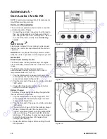
Addendum A -
Cam Locks / Arctic Kit
NOTE:
Location and configuration of kit components
may differ according to model.
Cam Lock Receptacles
The cam lock receptacles allow for quick connection
and disconnection of loads.
1. Connect the cam lock connectors from the load to
the cam lock receptacles on the lower portion of
the outlet panel on the unit. See Figure A1. Be sure
to connect the load correctly. See
Connecting
Loads
.
WARNING
Electrocution Hazard. Do not connect or disconnect
loads to the cam lock receptacles while the unit is in
operation.
NOTICE:
Do not operate the voltage selector switch
while the unit is in operation. Unit damage may result.
Arctic Kit
Block Heater / Battery Heater
The block heater / battery heater keeps the engine
block and battery heated while the unit is stored or not
in use.
The block heater / battery heater should be
used whenever the unit is stored or not in use in
temperatures below 32° F (0° C).
1. Plug the female end of a heavy-duty power cord
(not supplied) into the Block Heater / Battery Heater
recessed receptacle (A, Figure A2).
2. Plug the male end of the power cord into a standard
120V outlet.
3. Unplug the block heater / battery heater before
putting the unit into operation.
Battery Charger
The battery charger keeps the battery charged while
the unit is stored or not in use.
1. Plug the female end of a heavy-duty power cord
(not supplied) into the Battery Charger recessed
receptacle (B, Figure A2).
2. Plug the male end of the power cord into a standard
120V outlet.
3. The red light (A, Figure A3) on the battery charger
module, located in the left front section of the
engine compartment (see Figure A3) indicates the
battery is charging. The green light (B) indicates
full charge. (The battery charger can stay plugged
in after the battery reaches full charge without
damaging the battery.)
4. Unplug the battery charger before putting the unit
into operation.
Figure A1
Figure A2
Figure A3
Go
to
Discount-Equipment.com
to
order
your
parts
Summary of Contents for Maxi-Power MP65-8B1
Page 8: ...7 I A H B E G C F D K J G o to Discount Equipm ent com to order your parts ...
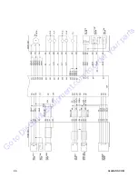
Page 39: ...38 ALLMAND COM Wiring Diagram Generator G o to Discount Equipm ent com to order your parts ...
Page 40: ...39 Engine G o to Discount Equipm ent com to order your parts ...
Page 41: ...40 ALLMAND COM G o to Discount Equipm ent com to order your parts ...
Page 44: ...43 Addendum B Tire Safety Information G o to Discount Equipm ent com to order your parts ...


