18
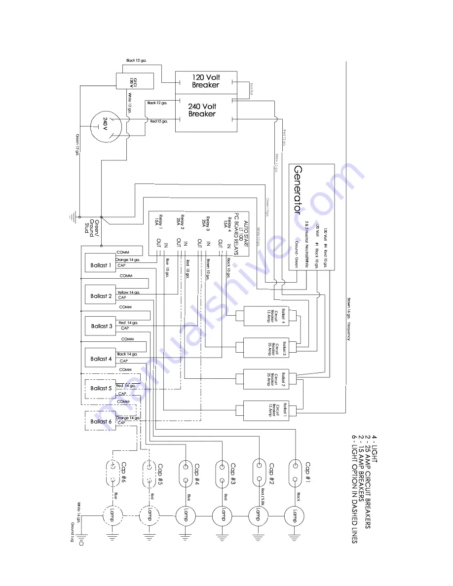
WI-LSC905/3003-02
Wiring Schematic for Cat/Perkins LSC100 LIGHT SEQUENCE CONTROLLER
with Photocell and Optional Timer
Not
for
Reproduction
Page 1: ...LSC905 01 LSC100 LIGHT SEQUENCE COMMANDER Operation Testing and Troubleshooting Information ALLMAND BROS INC P O BOX 888 HOLDREGE NE 68949 PHONE 308 995 4495 1 800 562 1373 ALLMAND FAX 308 995 5887 ALLMAND PARTS FAX 308 995 4883 LSC100 Light Sequence Commander N o t f o r R e p r o d u c t i o n ...
Page 2: ...ctions for Optional Timer Page 5 LSC100 Features and Benefits Page 6 Description of Load Sequencing Page 7 LSC100 Testing Procedure Page 8 Parts List Page 9 Wiring Schematic for Kubota LSC100 Pages 10 14 Wiring Schematic for Cat Perkins LSC100 Pages 15 19 LSC100 Logic Sequence Flow Chart Page 20 N o t f o r R e p r o d u c t i o n ...
Page 3: ...Down Automatic Start Instructions 1 Turn power switch ON 2 Turn light circuit breakers ON 3 Turn Auto Manual switch to AUTO Start sequence will begin when photocell senses preset light value NOTE Glow plugs are automatic as required Engine will start or make 5 attempts Lights will come on when engine water temperature reaches 120 F Shut Down 1 Turn Auto Manual switch OFF 2 Turn power switch OFF 1 ...
Page 4: ...t occurs and the red LED flashes Once the water temperature reaches 120 F the light relays begin to close sequentially with a three second delay in between NOTE Light circuit breakers must be in the ON position or the lights will not come on If the fuel level in the tank falls below 1 10 full the shut down sequence will begin The low fuel fault will be indicated by a flashing red LED It will remai...
Page 5: ... hour and the MIN key to set the minute NOTE You may never need to use more than 1 event ON and OFF per day However the timer is capable of 8 event pairs per day Always set an OFF time for each ON time NOTE To clear the event press the TIMER key until you get to the event you want to clear and hold then press the DAY key until the setting clears Always set an OFF time for each ON time It is possib...
Page 6: ...e engine will not require bleeding of the fuel system and the possible starter and solenoid failures as a result of overcranking 6 Sequenced light control Lights will come on automatically after the engine is started and will turn off automatically before engine is shut down This provides protection for the generator because the load will be OFF before the engine is shut down 7 Diagnostic LED Faul...
Page 7: ...motors etc 5 A smaller generator may be used as the loads can be sequenced on Some types of loads require a significant inrush to start such as electric motors etc 6 The engine can be started and allowed to warm up before loads are applied 7 The engine oiling system will be allowed to build up to normal oil pressures before the load is applied AUTOMATIC LOAD SEQUENCING OFF Generally an engine gene...
Page 8: ...Low Fuel Level Sequenced shutdown can be checked by starting the engine and allowing the lights to turn on After the lights are on remove the wire from the Fuel Sender and the unit will begin to sequence the lights OFF at three second intervals 2 Lights at a time if the machine has two lights on each breaker The red LED will also be flashing Within 30 seconds from the time the wire is removed the ...
Page 9: ...itch 650744 1 Temperature sender 3 8 NPT 650745 1 Engine harness 650746 3 Red LED lens 650747 1 Green LED lens 650748 1 Yellow LED lens 650749 1 ABS Plastic box 650750 1 Single pin connector for Starter 650741 1 Two pin connector for Alternator 650742 1 Three pin connector for Fuel Solenoid 650743 1 Photocell 650755 1 Timer Optional 352471 N o t f o r R e p r o d u c t i o n ...
Page 10: ...10 WI LSC905 3003 02 Wiring Schematic for Kubota LSC100 LIGHT SEQUENCE CONTROLLER with Photocell and Optional Timer N o t f o r R e p r o d u c t i o n ...
Page 11: ...11 WI LSC905 3003 02 Wiring Schematic for Kubota LSC100 LIGHT SEQUENCE CONTROLLER with Photocell and Optional Timer N o t f o r R e p r o d u c t i o n ...
Page 12: ...12 WI LSC905 3003 02 Wiring Schematic for Kubota LSC100 LIGHT SEQUENCE CONTROLLER with Photocell and Optional Timer N o t f o r R e p r o d u c t i o n ...
Page 13: ...13 WI LSC905 3003 02 Wiring Schematic for Kubota LSC100 LIGHT SEQUENCE CONTROLLER with Photocell and Optional Timer N o t f o r R e p r o d u c t i o n ...
Page 14: ...14 WI LSC905 3003 02 Wiring Schematic for Kubota LSC100 LIGHT SEQUENCE CONTROLLER with Photocell and Optional Timer N o t f o r R e p r o d u c t i o n ...
Page 15: ...15 WI LSC905 3003 02 Wiring Schematic for Cat Perkins LSC100 LIGHT SEQUENCE CONTROLLER with Photocell and Optional Timer N o t f o r R e p r o d u c t i o n ...
Page 16: ...16 WI LSC905 3003 02 Wiring Schematic for Cat Perkins LSC100 LIGHT SEQUENCE CONTROLLER with Photocell and Optional Timer N o t f o r R e p r o d u c t i o n ...
Page 17: ...17 WI LSC905 3003 02 Wiring Schematic for Cat Perkins LSC100 LIGHT SEQUENCE CONTROLLER with Photocell and Optional Timer N o t f o r R e p r o d u c t i o n ...
Page 18: ...18 WI LSC905 3003 02 Wiring Schematic for Cat Perkins LSC100 LIGHT SEQUENCE CONTROLLER with Photocell and Optional Timer N o t f o r R e p r o d u c t i o n ...
Page 19: ...19 WI LSC905 3003 02 LSC100 LIGHT SEQUENCE CONTROLLER Logic Sequence Flow Chart N o t f o r R e p r o d u c t i o n ...
Page 20: ...20 WI LSC905 3003 02 N o t f o r R e p r o d u c t i o n ...