background image

20

DIA

GNO

S

TIC TR

ANSMIS

SION MAIN C

ODE

S P2

64

1-P2

8

1B

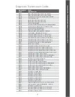
DIAGNOSTIC  

CODE

CODE 

DESCRIPTION

P2641

TORQUE MANAGEMENT FEEDBACK SIGNAL B

P2669

ACTUATOR SUPPLY CIRCUIT VOLTAGE 2 OPEN (HSD 2)

P2670

ACTUATOR SUPPLY CIRCUIT VOLTAGE 2 LOW (HSD 2)

P2671

ACTUATOR SUPPLY CIRCUIT VOLTAGE 2 HIGH (HSD 2)

P2684

ACTUATOR SUPPLY CIRCUIT VOLTAGE 3 OPEN (HSD 3)

P2685

ACTUATOR SUPPLY CIRCUIT VOLTAGE 3 LOW (HSD 3)

P2686

ACTUATOR SUPPLY CIRCUIT VOLTAGE 3 HIGH (HSD 3)

P26E7

ACTUATOR SUPPLY CIRCUIT VOLTAGE 4 OPEN (HSD 4)

P26E8

ACTUATOR SUPPLY CIRCUIT VOLTAGE 4 LOW (HSD 4)

P26E9

ACTUATOR SUPPLY CIRCUIT VOLTAGE 4 HIGH (HSD 4)

P2714

PRESSURE CONTROL SOLENOID (PCS) 4 STUCK OFF

P2715

PRESSURE CONTROL SOLENOID (PCS) 4 STUCK ON 

P2718

PRESSURE CONTROL SOLENOID (PCS) 4 CONTROL CIRCUIT OPEN

P2720

PRESSURE CONTROL SOLENOID (PCS) 4 CONTROL CIRCUIT LOW

P2721

PRESSURE CONTROL SOLENOID (PCS) 4 CONTROL CIRCUIT HIGH

P2723

PRESSURE CONTROL SOLENOID (PCS) 1 STUCK OFF

P2724

PRESSURE CONTROL SOLENOID (PCS) 1 STUCK ON

P2727

PRESSURE CONTROL SOLENOID (PCS) 1 CONTROL CIRCUIT OPEN

P2729

PRESSURE CONTROL SOLENOID (PCS) 1 CONTROL CIRCUIT LOW 

P2730

PRESSURE CONTROL SOLENOID (PCS) 1 CONTROL CIRCUIT HIGH 

P2732

PRESSURE CONTROL SOLENOID (PCS) 5 STUCK OFF

P2733

PRESSURE CONTROL SOLENOID (PCS) 5 STUCK ON

P2736

PRESSURE CONTROL SOLENOID (PCS) 5 CONTROL CIRCUIT OPEN

P2738

PRESSURE CONTROL SOLENOID (PCS) 5 CONTROL CIRCUIT LOW

P2739

PRESSURE CONTROL SOLENOID (PCS) 5 CONTROL CIRCUIT HIGH

P273F

RETARDER OIL TEMPERATURE SENSOR OVER TEMPERATURE CONDITION

P2742

RETARDER OIL TEMPERATURE SENSOR CIRCUIT LOW

P2743

RETARDER OIL TEMPERATURE SENSOR CIRCUIT HIGH

P274B

TRANSMISSION FLUID TEMPERATURE SENSOR “C” CIRCUIT 
RANGE/PERFORMANCE

P274C

TRANSMISSION FLUID TEMPERATURE SENSOR “C” CIRCUIT LOW

P274D

TRANSMISSION FLUID TEMPERATURE SENSOR “C” CIRCUIT HIGH

P274F

TRANSMISSION FLUID SENSOR “C” OVER TEMPERATURE 
CONDITION

P2761

TORQUE CONVERTER CLUTCH (TCC) PRESSURE CONTROL 
SOLENOID (PCS) CONTROL CIRCUIT/OPEN 

P2763

TORQUE CONVERTER CLUTCH (TCC) PRESSURE CONTROL 
SOLENOID (PCS) CONTROL CIRCUIT HIGH 

P2764

TORQUE CONVERTER CLUTCH (TCC) PRESSURE CONTROL 
SOLENOID (PCS) CONTROL CIRCUIT LOW 

P2789

TRANSMISSION CLUTCH LIFE EXPIRED (CLUTCH ADAPTIVE 
LEARNING AT LIMIT)

P2793

GEAR SHIFT DIRECTION CIRCUIT 

P2808

PRESSURE CONTROL SOLENOID (PCS) 6 STUCK OFF

P2809

PRESSURE CONTROL SOLENOID (PCS) 6 STUCK ON

P2812

PRESSURE CONTROL SOLENOID (PCS) 6 CONTROL CIRCUIT OPEN

P2814

PRESSURE CONTROL SOLENOID (PCS) 6 CONTROL CIRCUIT LOW

P2815

PRESSURE CONTROL SOLENOID (PCS) 6 CONTROL CIRCUIT HIGH

P2817

PRESSURE CONTROL SOLENOID (PCS) 7 STUCK OFF

P2818

PRESSURE CONTROL SOLENOID (PCS) 7 STUCK ON

P281B

PRESSURE CONTROL SOLENOID (PCS) 7 CONTROL CIRCUIT OPEN

Summary of Contents for shift selector

Page 1: ...SHIFT SELECTOR OIL LEVEL INFORMATION DIAGNOSTIC CODES AND PROGNOSTIC FEATURES FOR 3000 4000 SERIES AND TC10 ALLISON TRANSMISSIONS OPERATION CODE MANUAL ...

Page 2: ...rognostics Without Oil Level Sensor Prognostic Features 8 Accessing Prognostics 9 Resetting Prognostics 10 Exit Prognostics 10 Diagnostics Codes 11 Section 3 Without Prognostics With Oil Level Sensor Fluid Levels 12 Checking Fluid Levels 12 Diagnostics Codes 14 Section 4 Without Prognostics Without Oil Level Sensor Diagnostics Codes 15 Diagnostics Transmission Codes Codes P0122 P077F 17 Codes P079...

Page 3: ... will be able to monitor transmission oil levels read diagnostic codes and prognostic information This manual will help you understand shift selector readouts and enjoy long trouble free operation of your Allison Automatic Diagnostics The Transmission Control Module TCM of your Allison Automatic monitors the transmission s electronic controls and when a problem condition is detected it May restric...

Page 4: ...e vehicles equipped with 5th Generation Electronic Controls If your vehicle is not equipped with an Allison supplied shift selector contact your OEM Mode Button Allison Automatics offer primary and secondary shift schedule modes to enhance performance or fuel economy The vehicle always defaults to the primary mode MODE is not shown on graphic display If equipped as such you can switch to the secon...

Page 5: ...il level information To enter the oil level function 1 Park the vehicle on a level surface shift to N NEUTRAL and apply the parking brake 2 Using a pushbutton shift selector simultaneously press the UP and DOWN arrows one time For a bump lever shift selector press the DIAGNOSTICS button one time 3 The fluid level reading will be delayed until the following conditions are met Engine must be at idle...

Page 6: ... exit the oil level function For pushbutton shift selector press N NEUTRAL button For bump lever shift selector press the DIAGNOSTICS button until you return to range display Prognostic Features 5th Generation Electronic Controls Shift Selectors display prognostics in text form to provide at a glance status of Oil Life Filter Life and Transmission Health The WRENCH ICON will illuminate briefly aft...

Page 7: ...rognostics through the shift selector Oil Life Monitor For a pushbutton shift selector simultaneously press the UP and DOWN arrows two times For a bump lever shift selector press the DIAGNOSTICS button two times Filter Life Monitor For a pushbutton shift selector simultaneously press the UP and DOWN arrows three times For a bump lever shift selector press the DIAGNOSTICS button three times Transmi...

Page 8: ...ump lever shift selector press and hold the MODE button for approximately 10 seconds while in Filter Life Monitor mode Or For either a pushbutton or bump lever shift selector perform the following shift sequence with the ignition on but the engine off Do not stop the sequence for more than three seconds once you have started N R N R N D N Transmission Health Monitor This must be reset manually usi...

Page 9: ...es still in the memory ACTIVE CODES INACTIVE CODES For a detailed list of Diagnostic Transmission Codes for 5th Generation Electronic Controls Shift Selectors see pages 17 through 21 To exit the diagnostic code function Any of the following methods may be used 1 For a pushbutton shift selector press the N NEUTRAL range button 2 For a bump lever shift selector press the DIAGNOSTICS range button unt...

Page 10: ...o indicate that prognostics are enabled If the WRENCH ICON remains on or flashes this indicates there is a service issue relating to clutch filter or fluid life Oil Life Monitor The status of the oil life is displayed as a percentage OIL LIFE 100 until fluid is due for a change Filter Life Monitor The status of filter life is displayed as OIL FILTERS OK and alerts when filters are due for a change...

Page 11: ...DIAGNOSTICS button one time Filter Life Monitor For a pushbutton shift selector simultaneously press the UP and DOWN arrows two times For a bump lever shift selector press the DIAGNOSTICS button two times Transmission Health Monitor For a pushbutton shift selector simultaneously press the UP and DOWN arrows three times For a bump lever shift selector press the DIAGNOSTICS button three times The pe...

Page 12: ...bump lever shift selector press and hold the MODE button for approximately 10 seconds while in Filter Life Monitor mode Or For either a pushbutton or bump lever shift selector perform the following shift sequence with the ignition on but the engine off Do not stop the sequence for more than three seconds once you have started N R N R N D N Transmission Health Monitor This must be reset manually us...

Page 13: ... in the memory ACTIVE CODES INACTIVE CODES For a detailed list of Diagnostic Transmission Codes for 5th Generation Electronic Controls Shift Selectors see pages 17 through 21 To exit the diagnostic code function Any of the following methods may be used 1 For a pushbutton shift selector press the N NEUTRAL range button 2 For a bump lever shift selector press the DIAGNOSTICS range button until back ...

Page 14: ...uid Levels Use the following procedure to display oil level information To enter the oil level function 1 Park the vehicle on a level surface shift to N NEUTRAL and apply the parking brake 2 Using a pushbutton shift selector simultaneously press the UP and DOWN arrows one time For a bump lever shift selector press the DIAGNOSTICS button one time 3 The fluid level reading will be delayed until the ...

Page 15: ...f quarts the transmission oil is low HIGH FLUID LEVEL The display shows the number of quarts the transmission oil is overfilled Delayed Fluid Level Check If the fluid level check cannot be completed one of the following Oil Level Display faults will be shown To exit the oil level function For pushbutton shift selector press N NEUTRAL button one time For bump lever shift selector press the DIAGNOST...

Page 16: ...CODES INACTIVE CODES For a detailed list of Diagnostic Transmission Codes for 5th Generation Electronic Controls Shift Selectors see pages 17 through 21 To exit the diagnostic code function Any of the following methods may be used 1 For a pushbutton shift selector press the N NEUTRAL range button 2 For a bump lever shift selector press the DIAGNOSTICS range button until back to range display 3 Wai...

Page 17: ...or a bump lever shift selector press the DIAGNOSTICS button one time 3 Up to five codes may be recorded in memory 4 Each code remains in the display until the MODE button is pushed then the next code is shown Active codes are shown first newest to oldest followed by any inactive codes still in the memory ACTIVE CODES INACTIVE CODES For a detailed list of Diagnostic Transmission Codes for 5th Gener...

Page 18: ... the DIAGNOSTICS range button until back to range display 3 Wait approximately 10 minutes and the system will automatically return to normal operating mode 4 Turn off the vehicle engine ignition switch Drive the vehicle and check for code recurrence If codes continue to recur bring the vehicle to an Allison Authorized Service Network to diagnose and repair the problem causing the codes ...

Page 19: ...SOR CIRCUIT HIGH P070C TRANSMISSION FLUID LEVEL SENSOR CIRCUIT LOW P070D TRANSMISSION FLUID LEVEL SENSOR CIRCUIT HIGH P0712 TRANSMISSION FLUID TEMPERATURE SENSOR CIRCUIT LOW P0713 TRANSMISSION FLUID TEMPERATURE SENSOR CIRCUIT HIGH P0715 TURBINE SHAFT SPEED SENSOR CIRCUIT P0716 TURBINE SHAFT SPEED SENSOR CIRCUIT PERFORMANCE P0717 TURBINE SHAFT SPEED SENSOR CIRCUIT NO SIGNAL P071A NEUTRAL AT STOP IN...

Page 20: ...PUT SIGNAL PERFORMANCE P0882 TCM POWER INPUT SIGNAL LOW P0883 TCM POWER INPUT SIGNAL HIGH P088A TRANSMISSION FILTER MAINTENANCE ALERT P088B TRANSMISSION FILTER MAINTENANCE REQUIRED P0894 UNEXPECTED MECHANICAL GEAR DISENGAGEMENT P0897 TRANSMISSION FLUID DETERIORATED P0960 MAIN PRESSURE MODULATION SOLENOID CONTROL CIRCUIT OPEN P0961 MAIN PRESSURE MODULATION SOLENOID SYSTEM PERFORMANCE P0962 MAIN PRE...

Page 21: ... P1903 COUNTERSHAFT SPEED SENSOR NO ACTIVITY P1907 SHIFT FORK STUCK MOVING TO REVERSE POSITION P1922 TRANSMISSION FLUID PRESSURE SWITCH A CIRCUIT LOW P1923 TRANSMISSION FLUID PRESSURE SWITCH A CIRCUIT HIGH P1927 TRANSMISSION FLUID PRESSURE SWITCH B CIRCUIT LOW P1928 TRANSMISSION FLUID PRESSURE SWITCH B CIRCUIT HIGH P192C TRANSMISSION FLUID PRESSURE SWITCH C CIRCUIT LOW P192D TRANSMISSION FLUID PRE...

Page 22: ...ENOID PCS 5 STUCK ON P2736 PRESSURE CONTROL SOLENOID PCS 5 CONTROL CIRCUIT OPEN P2738 PRESSURE CONTROL SOLENOID PCS 5 CONTROL CIRCUIT LOW P2739 PRESSURE CONTROL SOLENOID PCS 5 CONTROL CIRCUIT HIGH P273F RETARDER OIL TEMPERATURE SENSOR OVER TEMPERATURE CONDITION P2742 RETARDER OIL TEMPERATURE SENSOR CIRCUIT LOW P2743 RETARDER OIL TEMPERATURE SENSOR CIRCUIT HIGH P274B TRANSMISSION FLUID TEMPERATURE ...

Page 23: ...ER REQUEST SENSOR CIRCUIT LOW C1313 RETARDER REQUEST SENSOR CIRCUIT HIGH U0073 CAN COMMUNICATION BUS 1 OFF U0074 CAN COMMUNICATION BUS 2 OFF U0100 LOST COMMUNICATIONS WITH ECM A U0103 LOST COMMUNICATION WITH GEAR SHIFT MODULE 1 U0110 LOST COMMUNICATION WITH DRIVE MOTOR CONTROL MODULE U0111 LOST COMMUNICATION WITH ENERGY STORAGE SYSTEM CONTROL MODULE U0287 LOST COMMUNICATION WITH ELECTRIC PUMP U029...

Page 24: ...d 2014 Allison Transmission Inc All rights reserved allisontransmission com Information contained in this brochure is designed to give you an overview of the Oil Level Sensor Diagnostics and Prognostic Features on your Allison Automatic and is not intended to replace your Operator s Manual To order an Operator s Manual go to allisontransmission com or call toll free 888 666 5799 ...

Reviews: