background image

506724-01

Page 28 of 57

Issue 1108

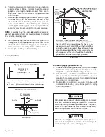
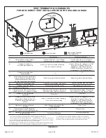
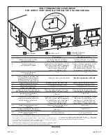
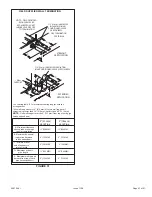
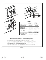
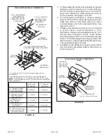
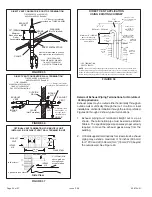
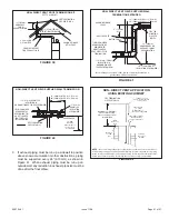
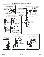
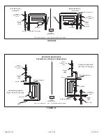
FIGURE 32

C

A

E

D

B

A

B

D

D

B

C

A

C

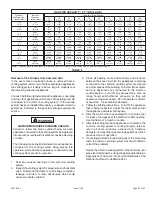
12"

1

1

2

2

2" (51mm)

Vent Pipe

3" (76mm)

Vent Pipe

A

− Clearance above

grade or average snow

accumulation

B

−Horizontal

    separation between 

    intake and exhaust

C

−Minimum from

end of exhaust to

inlet of intake

D

−Exhaust pipe length

E

−Wall support distance

from top of each pipe

(intake/exhaust)

12" (508MM) Min.

12" (508MM) Min.

6" (152MM) Min.

24" (610 MM) Max

9" (227MM) Min.

12" (305MM) Min.
16" (405 MM) Max.

6" (152MM) Max.

6" (152MM) Min.

24" (610 MM) Max

9" (227MM) Min.

12" (305MM) Min.
20" (508MM) Max.

6" (152MM) Max.

TABLE 7

The exhaust termination tee should be connected to the 2" or 3" PVC flue pipe as shown in the illustration. Do

not use an accelerator in applications that include an exhaust termination tee. The accelerator is not required.

As required. Flue gas may be acidic and may adversely affect some building materials. If a side wall vent

termination is used and flue gases will impinge on the building materials, a corrosion−resistant shield (24 inches
square) should be used to protect the wall surface. If optional tee is used, the protective shield is recom-
mended. The shield should be constructed using wood, sheet metal or other suitable material. All seams, joints,
cracks, etc. in affected area, should be sealed using an appropriate sealant.

3

Exhaust pipe 45° elbow can be rotated to the side away from the combustion air inlet to direct exhaust away

from adjacent property. The exhaust must never be directed toward the combustion air inlet.

NOTE

 − See unit installation instructions for proper exhaust pipe termination size reduction.

Front View of

Intake and Exhaust

Intake

Exhaust

3

Intake

Exhaust

Summary of Contents for 92G1UH

Page 1: ...med by a licensed professional installer or equivalent service agency or the gas supplier WARNING Manufactured By Allied Air Enterprises Inc A Lennox International Inc Company 215 Metropolitan Drive West Columbia SC 29170 Unit Dimensions 2 A95 A93 95G1 92G1UH Parts Arrangement 3 A95 A93 95G1 92G1UH Gas Furnace 4 Shipping and Packing List 4 Safety Information 4 Use of Furnace as a Construction Heat...

Page 2: ...lumes of 1800 cfm 850 L s or greater must have one of the following 1 Single side return air with transition to accommodate 20 x 25 x 1 in 508 x 635 x 25 mm cleanable air filter Required to maintain proper air velocity 2 Single side return air with optional RAB Return Air Base 3 Bottom return air 4 Return air from both sides 5 Bottom and one side return air See Blower Performance Tables for additi...

Page 3: ...506724 01 Page 3 of 57 Issue 1108 EXPANDED VIEW Figure 1 ...

Page 4: ...l injury can result from contact with sharp sheet metal edges Be careful when you handle this equipment CAUTION DANGER OF EXPLOSION DANGER There are circumstances in which odorant used with LP Propane gas can lose its scent In case of a leak LP Propanegaswillsettleclosetothefloorandmaybedifficult to smell An LP Propane leak detector should be installed in all LP applications Use only the type of g...

Page 5: ...t be electrically grounded according to local codes In addition in the United States installation must conform with the current National Electric Code ANSI NFPANo 70 The National Electric Code ANSI NFPA No 70 is available from the following address National Fire Protection Association 1 Battery March Park Quincy MA 02269 In Canada all electrical wiring and grounding for the unit must be installed ...

Page 6: ...shall be installed by a licensed plumber or fitter only The gas cock must be T handle type When a furnace is installed in an attic the passageway to and service area surrounding the equipment shall be floored Combustion Dilution Ventilation Air If this unit is installed as a Non Direct Vent Furnace follow the guidelines in this section NOTE In Non Direct Vent Installations combustion air is taken ...

Page 7: ...a door Though an area may appear to be unconfined it might be necessary to bring in outdoor air for combustion if the structure does not provide enough air by Do not install the furnace in a corrosive or contaminated atmosphere Meet all combustion and ventilation air requirements as well as all local codes CAUTION infiltration If the furnace is located in a building of tight construction with weat...

Page 8: ...protective covering is not known for calculating the size opening required it may be assumed that wood louvers will have 20 to 25 percent free area and metal louvers and grilles will have 60 to 75 percent free area Louvers and grilles must be fixed in the open position or interlocked with the equipment so that they are opened automatically during equipment operation FIGURE 5 EQUIPMENT IN CONFINED ...

Page 9: ...ee flexible legs and one rigid leg The rigid leg is equipped with a shipping bolt and a flat white plastic washer rather than the rubber mounting grommet used with a flexible mounting leg See Figure 8 The bolt and washer must be removed before the furnace is placed into operation After the bolt and washer have been removed the rigid leg will not touch the blower housing WARNING Blower access panel...

Page 10: ...al between the bottom of the furnace and the platform to ensure that the furnace operates properly and safely The furnace is equipped with a removable bottom panel to facilitate installation Markings are provided on both sides of the furnace cabinet for installations that require side return air Cut the furnace cabinet at the maximum dimensions shown on page 2 Furnace applications which include si...

Page 11: ...d to accommodate plenum or IAQ cabinet while maintaining dimensions shown Side return air openings must be cut in the field There are cutting guides stenciled on the cabinet for the side return air opening The size of the opening must not extend beyond the markings on the furnace cabinet 2 To minimize pressure drop the largest opening height possible up to 14 inches is preferred FRONT VIEW 1 Unit ...

Page 12: ...ate line into a condensate pump to meet drain line slope requirements The pump must be rated for use with condensing furnaces Protect the condensate discharge line from the pump to the outside to avoid freezing 6 Continue with exhaust condensate and intake piping installation according to instructions Typical Horizontal Application Figure 16 This furnace can be installed in horizontal applications...

Page 13: ... room a negative pressure is created in the room If a gas appliance is operating in a room with negative pressure the flue products can be pulled back down the vent pipe and into the room This reverse flow of the flue gas may result in incomplete combustion and the formation of carbon monoxide gas This raw gas or toxic fumes might then be distributed throughout the house by the furnace duct system...

Page 14: ... pipe to the flue collar or to bond the 90 elbow or reducing 90 elbow to the flue collar In addition the first three feet of vent pipe from the furnace flue collar must be accessible for inspection Solvent cements for plastic pipe are flammable liquids and should be kept away from all sources of ignition Do not use excessive amounts of solvent cement when making joints Good ventilation should be m...

Page 15: ... into operation DANGER NOTE A sheet metal screw may be used to secure the intake pipe to the connector if desired Use a drill or self tapping screw to make a pilot hole TABLE 3 OUTDOOR TERMINATION KITS USAGE A95UH A93UH 95G1UH 92G1UH VENT PIPE DIA in STANDARD CONCENTRIC Outdoor Exhaust Accelerator Dia X Length Outdoor Exhaust Accelerator Dia X Length Flush Mount Kit 1 1 2 Concentric Kit 2 Concentr...

Page 16: ...condensate collection from trap and lines 3 Route piping to outside of structure Continue with installation following instructions given in piping termination section The exhaust vent pipe operates under positive pressure and must be completely sealed to prevent leakage of combustion products into the living space CAUTION Do not discharge exhaust into an existing stack or stack that also serves an...

Page 17: ...pipe A 2 elbow must be added before the pipe is transitioned to any size larger than 2 This elbow must be added to the elbow count used to determine acceptable vent lengths Contact the Application Department for more information concerning sizing of vent systems which include multiple pipe sizes Do not use screens or perforated metal in exhaust or intake terminations Doing so will cause freeze ups...

Page 18: ...8 23 117 117 98 98 94 5 56 41 19 90 75 43 18 112 112 93 93 89 6 51 36 14 85 70 38 13 107 107 88 88 84 7 46 31 9 80 65 33 8 102 102 83 83 79 8 41 26 n a 75 60 28 n a 97 97 78 78 74 9 36 21 70 55 23 92 92 73 73 69 10 31 16 65 50 18 87 87 68 68 64 Concentric Termination Elevation 0 10 000 Number Of 90 Elbows Used 2 Pipe 2 1 2 Pipe 3 Pipe Model Model Model 045 070 090 110 135 045 070 090 110 135 045 0...

Page 19: ... a 85 70 44 19 101 101 94 94 85 5 48 33 17 80 65 39 14 96 96 89 89 80 6 43 28 12 75 60 34 9 91 91 84 84 75 7 38 23 7 70 55 29 n a 86 86 79 79 70 8 33 18 n a 65 50 24 81 81 74 74 65 9 28 13 60 45 19 76 76 69 69 60 10 23 8 55 40 14 71 71 64 64 55 Standard Termination at Elevation 4 501 10 000 Number Of 90 Elbows Used 2 Pipe 2 1 2 Pipe 3 Pipe Model Model Model 045 070 090 110 135 045 070 090 110 135 ...

Page 20: ...e shortest length of 2 PVC pipe possible NOTE Exhaust pipe and intake pipe must be the same diameter or FIGURE 23 TRANSITION SIDE VIEW 2 2 2 2 or TYPICAL EXHAUST PIPE CONNECTIONS IN HORIZONTAL DIRECT OR NON DIRECT VENT APPLICATIONS RIGHT HAND DISCHARGE SHOWN 3 2 45 MAX 45 MAX DO NOT transition from smaller to larger pipe in horizontal runs of exhaust pipe EXHAUST 12 max 2 2 When transitioning up i...

Page 21: ...utdoors and flue gases are discharged outdoors The provided air intake screen must not be used in direct vent applications outdoors FIGURE 24 TYPICAL AIR INTAKE PIPE CONNECTIONS IN UPFLOW DIRECT VENT APPLICATIONS 2 TRANSITION 2 3 Pipe size determined in table 5 2 2 2 2 or AIR INTAKE When transitioning up in pipe size use the shortest length of 2 PVC pipe possible NOTE Intake and exhaust pipe must ...

Page 22: ...ctions Refer to Table 5 for pipe sizes FIGURE 26 TYPICAL AIR INTAKE PIPE CONNECTIONS UPFLOW NON DIRECT VENT APPLICATIONS INTAKE DEBRIS SCREEN Provided NOTE Debris screen and elbow may be rotated so that screen may be positioned to face forward or to either side FIGURE 27 TYPICAL AIR INTAKE PIPE CONNECTIONS HORIZONTAL NON DIRECT VENT APPLICATIONS Horizontal Right Hand Air Discharge Application Show...

Page 23: ...on position termination so it is free from any obstructions and 12 above the average snow accumulation At vent termination care must be taken to maintain protective coatings over building materials prolonged exposure to exhaust condensate can destroy protective coatings It is recommended that the exhaust outlet not be located within 6 feet 1 8 m of a condensing unit because the condensate can dama...

Page 24: ...chanical air supply inlet to building or the com bustion air inlet to any other ap pliance Clearance to mechanical air sup ply inlet Clearance above paved sidewalk or paved driveway located on public property Clearance under veranda porch deck or balcony 12 Equal to or greater than soffit depth 3 feet 9m 12 3 feet 9m within a height 15 feet 4 5m above the meter regulator assembly 3 feet 9m 6 inche...

Page 25: ...o building or the com bustion air inlet to any other ap pliance Clearance to mechanical air sup ply inlet Clearance above paved sidewalk or paved driveway located on public property Clearance under veranda porch deck or balcony 12 7 feet 2 1m 3 feet 9m within a height 15 feet 4 5m above the meter regulator assembly 3 feet 9m 6 inches 152mm for appliances 10 000 Btuh 3kw 9 inches mm for appliances ...

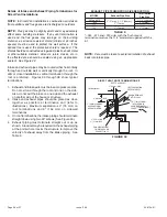
Page 26: ...Also do not exit the intake on one side and the exhaust on another side of the house or structure 2 Intake and exhaust pipes should be placed as close together as possible at termination end refer to illustrations Maximum separation is 3 76 mm on roof terminations and 6 152 mm on sidewall terminations 3 On roof terminations the intake piping should terminate straight down using two 90 elbows See F...

Page 27: ...w accumulation B Maximum horizontal separation between intake and exhaust C Minimum from end of exhaust to inlet of intake D Maximum exhaust pipe length E Maximum wall support distance from top of each pipe intake exhaust 12 508MM 12 508MM 6 152MM 6 152MM 8 203MM 8 203MM 12 305MM 20 508MM 6 152MM 6 152MM NOTE FIELD PROVIDED REDUCER MAY BE REQUIRED TO ADAPT LARGER VENT PIPE SIZE TO TERMINATION D B ...

Page 28: ...ust termination tee The accelerator is not required 2 As required Flue gas may be acidic and may adversely affect some building materials If a side wall vent termination is used and flue gases will impinge on the building materials a corrosion resistant shield 24 inches square should be used to protect the wall surface If optional tee is used the protective shield is recom mended The shield should...

Page 29: ... FOR 2 PVC PIPE 1 EXTENSION FOR 3 PVC PIPE FIGURE 34 1 1 2 ACCELERATOR all 45 070 and 090 units FURNACE EXHAUST PIPE FURNACE INTAKE PIPE 4 GLUE EXHAUST END FLUSH INTO TERMINATION FLAT SIDE FLUSH MOUNT SIDE WALL TERMINATION 51W11 FIGURE 33 FIELD SUPPLIED WALL TERMINATION See venting table 5 for maximum venting lengths with this arrangement Use wall support every 24 610 mm Use two wall supports if e...

Page 30: ...on FIGURE 36 DIRECT VENT CONCENTRIC WALL TERMINATION 71M80 69M29 or 60L46 US 44W92 or 44W93 Canada INTAKE AIR INTAKE AIR INTAKE AIR OUTSIDE WALL GRADE CLAMP Not Furnished FIELD PROVIDED REDUCER MAY BE REQUIRED TO ADAPT LARGER VENT PIPE SIZE TO TERMINATION EXHAUST VENT 1 1 2 38mm accelerator provided on 71M80 44W92 EXHAUST VENT FIGURE 37 EXHAUST VENT INTAKE AIR 5 1 2 140mm Front View 12 305mm 5 127...

Page 31: ...MULATION UNCONDITIONED SPACE 1 2 13mm FOAM INSULATION IF REQUIRED 1 2 13mm FOAM INSULATION IN UNCONDITIONED SPACE IF REQUIRED WALL SUPPORT OUTSIDE WALL SIZE TER MINATION PIPE PER TABLE 6 FIELD PROVIDED REDUCER MAY BE REQUIRED TO ADAPT LARGER VENT PIPE SIZE TO TERMINATION Use wall support every 24 610 Use two supports if extension is greater than 24 but less than 48 12 305mm MAX for 2 51mm 20 508mm...

Page 32: ...ope from the furnace to the drain 5 Install field provided vent on trap assembly as shown in Figures 44 through 46 Trap must extend at least 1 above the furnace condensate drain connection in upflow applications and 4 1 2 above the bottom of the cabinet in horizontal applications 6 If unit will be started immediately upon completion of installation prime trap per procedure outlined in Unit Start U...

Page 33: ...mote trap 5 max To Drain PVC Pipe Only Field Provided Vent Min 1 Above Condensate Drain Connection 1 Min Trap can be installed a maximum 5 from furnace Piping from furnace must slope down a minimum of 1 4 per ft toward trap CAUTION A separate drain line must be run to the drain from the condensate trap to ensure proper drainage and pressure switch operation DO NOT connect the condensate trap drain...

Page 34: ...ain To Drain 90 Elbow 3 4 inch PVC Not Furnished To Drain 90 Elbow 1 2 inch PVC Not Furnished 1 2 inch PVC Pipe Not Furnished Drain Assembly for 3 4 inch Drain Pipe OPTIONAL Drain Piping OPTIONAL Condensate Drain Connection 90 Street Elbow 1 2 inch PVC Not Furnished Condensate Drain Connection In Unit Adapter 1 2 inch slip X 1 2 inch mpt Not Furnished 1 inch 25mm Minimum Above Top of Condensate Dr...

Page 35: ...d for gas leaks Use a leak detecting solution or other preferred means Never use an open flame to test for gas leaks Check all connections using a commercially available soap solution made specifically for leak detection The furnace must be isolated from the gas supply system by closing its individual manual shut off valve during any pressure testing of the gas supply system at pressures more than...

Page 36: ...Gas Valve Bellows Grommet FIGURE 49 Horizontal Applications Possible Gas Piping Configurations GROUND JOINT UNION DRIP LEG MANUAL MAIN SHUT OFF VALVE GROUND JOINT UNION DRIP LEG MANUAL MAIN SHUT OFF VALVE GROUND JOINT UNION DRIP LEG MANUAL MAIN SHUT OFF VALVE Horizontal Application Left Side Air Discharge Horizontal Application Right Side Air Discharge NOTE BLACK IRON PIPE ONLY TO BE ROUTED INSIDE...

Page 37: ... at the draft hood relief opening Use the flame of a match or candle 6 After determining that each appliance connected to the common venting system is venting properly step 3 return all doors windows exhaust fans fireplace dampers and any other gas burning appliances to their previous mode of operation 7 If a venting problem is found during any of the preceding tests the common venting system must...

Page 38: ...gh for servicing at a later date Make sure that thermostat wire is long enough to facilitate future removal of blower for service Complete the wiring connections to the equipment Use the provided unit wiring diagram and the field wiring diagram shown in Figure 54 Use 18 gauge wire or larger that is suitable for Class II rating for thermostat connections Electrically ground the unit according to lo...

Page 39: ...temporary power Generator should have a wave form distortion of less than 5 THD total harmonic distortion terminals If a humidifier rated at greater than one amp is connected to this terminal it is necessary to use an external relay See Figure 56 for control board configuration This terminal is energized in the heating mode when the combustion air inducer is operating Install the room thermostat a...

Page 40: ...506724 01 Page 40 of 57 Issue 1108 TYPICAL WIRING DIAGRAM Figure 55 ...

Page 41: ...than air and will settle on the floor The gas valve on the unit is equipped with a gas control switch lever Use only your hand to move switch Never use tools If the switch will not move by hand do not try to repair it Force or attempted repair may result in a fire or explosion Placing the furnace into operation This furnace is equipped with an automatic hot surface ignition system Do not attempt t...

Page 42: ...s initially started steps 1 through 11 may need to be repeated to purge air from gas line 12 If the appliance will not operate follow the instructions Turning Off Gas to Unit and call your service technician or gas supplier Turning Off Gas to Unit 1 Set the thermostat to the lowest setting 2 Turn off all electrical power to the unit if service is to be performed 3 Remove the upper access panel 4 M...

Page 43: ...ral gas should burn blue 4 After allowing unit to stabilize for 5 minutes record manifold pressure and compare to value given in Table 9 NOTE Shut unit off and remove manometer as soon as an accurate reading has been obtained Take care to remove barbed fitting and replace threaded plug Proper Combustion Furnace should operate minimum 15 minutes with correct manifold pressure and gas flow rate befo...

Page 44: ...s factory set No adjustment necessary All models use the factory installed pressure switch from 0 7 500 feet Unit Size 0 4 500 ft 0 1 373 m 4 501 7 500 ft 1 373 2 286 m 7 501 10 000 ft 2 286 3 038 m 045 No Change No Change 74W90 070 No Change 77W43 73W22 090 No Change 77W42 73W22 110 No Change 77W43 73W22 135 No Change 77W42 73W22 Pressure switch is factory set No adjustment necessary All models u...

Page 45: ... 2 Visually inspect the venting system for proper size and horizontal pitch Determine there is no blockage or restriction leakage corrosion or other deficiencies which could cause an unsafe condition 3 To the extent that it is practical close all building doors and windows and all doors between the space in which the appliances connected to the venting system are located and other spaces of the bu...

Page 46: ...board speed terminal 7 Re secure blower access panel 8 Turn on electrical power to furnace 9 Recheck temperature rise Electronic Ignition The integrated control has an added feature of an internal Watchguard control The feature serves as an automatic reset device for integrated control lockout caused by ignition failure This type of lockout is usually due to low gas line pressure After one hour of...

Page 47: ...5 1425 665 1225 530 0 10 1950 865 1755 770 1430 630 1215 515 0 20 1935 840 1675 735 1455 610 1230 505 0 30 1885 810 1660 685 1410 585 1200 485 0 40 1830 780 1585 645 1385 570 1190 470 0 50 1750 740 1565 630 1320 535 1165 455 0 60 1660 695 1485 585 1280 505 1105 425 0 70 1540 665 1380 555 1230 485 1060 405 0 80 1420 615 1290 520 1140 445 945 375 0 90 1290 575 1175 470 1045 410 850 350 A93UH1D 92G1U...

Page 48: ...5 1315 590 0 90 1680 1000 1575 805 1440 670 1275 565 1700 1025 1590 835 1430 690 1210 565 A93UH1D 92G1UH 135 20D PERFORMANCE Less Filter External Static Pressure in w g Air Volume Watts at Different Blower Speeds Bottom Return Air Side Return Air with Optional Return Air Base Return Air from Both Sides or Return Air from Bottom and One Side Single Side Return Air Air volumes in bold in order to ma...

Page 49: ... 1300 465 1165 390 0 80 1455 560 1410 495 1195 430 1035 365 0 90 1300 515 1305 465 1100 390 900 320 A95UH1D 95G1UH 045 08B PERFORMANCE Less Filter External Static Pressure in w g Air Volume Watts at Various Blower Speeds High Medium High Medium Low Low cfm Watts cfm Watts cfm Watts cfm Watts 0 00 1140 455 920 365 765 295 710 265 0 10 1135 445 900 360 765 290 690 255 0 20 1125 430 895 350 755 285 6...

Page 50: ... 1350 610 0 90 1645 1010 1520 840 1340 705 1400 595 1595 1010 1540 830 1445 695 1315 600 A95UH1D 95G1UH 135 20D PERFORMANCE Less Filter External Static Pressure in w g Air Volume Watts at Different Blower Speeds Bottom Return Air Side Return Air with Optional Return Air Base Return Air from Both Sides or Return Air from Bottom and One Side Single Side Return Air Air volumes in bold in order to mai...

Page 51: ...empty water Inspect the trap then reinstall the clean out cap Cleaning Heat Exchanger If cleaning the heat exchanger becomes necessary follow the below procedures and refer to Figure 1 when disassembling unit Use papers or protective covering in front of furnace while removing heat exchanger assembly 1 Turn off electrical and gas supplies to the furnace 2 Remove the burner access panel 3 Mark all ...

Page 52: ...nd cold end header box 39 Secure burner assembly to vestibule panel using four existing screws Burners are self aligning to center of clam shells 40 Reconnect gas supply line to gas valve 41 Reconnect flame rollout switch wires 42 Reconnect sensor wire and reconnect 2 pin plug from ignitor 43 Reconnect wires to gas valve 44 Replace the blower compartment access panel 45 Refer to instruction on ver...

Page 53: ...al between the return air and the room where the furnace is installed Return air duct Must be properly attached and provide an air seal to the unit Operating performance Unit must be observed during operation to monitor proper performance of the unit and the vent system Combustion gases Flue products should be analyzed and compared to the unit specifications Problems detected during the inspection...

Page 54: ...quivalent service agency or gas supplier Cabinet Parts Upper Access Panel Blower Access Panel Top Cap Control Panel Parts Transformer Integrated Control Board Door Interlock Switch Blower Parts Blower Wheel Motor Motor Mounting Frame Motor Capacitor Blower Housing Cutoff Plate Heating Parts Flame Sensor Heat Exchanger Assembly Gas Manifold Combustion Air Inducer Gas Valve Main Burner Cluster Main ...

Page 55: ...alled Properly Pipes Supported Condensate Trap Primed Line Sloped Heat Cable Installed and Operable if applicable 2 2 2 1 Horizontal Pipes Sloped if applicable UNIT SET UP 3 4 Flter RETURN AIR Furnace Model Number_______________ Serial Number_________________ 3 DUCT SYSTEM SUPPLY AIR DUCT Sealed Insulated if necessary RETURN DUCT Sealed Filter Installed and Clean Grilles Unobstructed 4 VOLTAGE CHE...

Page 56: ...IC 5 Supply External Static _______ Return External Static ______ Total External Static _______ CONDENSATE LINE 6 Leak Free VENT PIPE 7 Leak Free COOLING MODE INDOOR BLOWER AMPS______ 3 TEMPERATURE DROP Return Duct Temperature _________ Supply Duct Temperature _ _______ Temperature Drop _________ 4 DRAIN LINE 8 Leak Free THERMOSTAT Adjusted and Programmed Explained Operation to Owner 9 SUPPLY AIR ...

Page 57: ...imum height of eight 8 feet above grade directly in line with the exhaust vent terminal for the horizontally vented gas fueled heating appliance or equipment The sign shall read in print size no less than one half 1 2 inch in size GAS VENT DIRECTLY BELOW KEEP CLEAR OF ALL OBSTRUCTIONS 4 INSPECTION The state or local gas inspector of the side wall horizontally vented gas fueled equipment shall not ...

Reviews: