


508187-01
Issue 2116
Page 10 of 51
80G2UH1
10CE20 / 80G2UH1
10CE20L
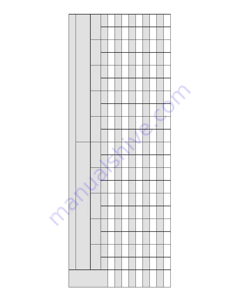
External Static Pressure
in. w
.g.
Air V
olume / W
atts at Different Blower Speeds
Bottom Return
Air
, Side Return
Air from Both Sides or Return
Air from Bottom and
One Side.
Single Side Return
Air -
Air volumes in bold (over 1800 cfm) require Optional Return
Air Base and field fabricated transition to accommodate 20 x 25 x 1 in. air filter in
order to maintain proper air velocity
.
High
(Black)
Medium-High
(Brown)
Medium
(Blue)
Medium-Low
(Y
ellow)
Low
(Red)
High
(Black)
Medium-High
(Brown)
Medium
(Blue)
Medium-Low
(Y
ellow)
Low
(Red)
cfm
W
atts
cfm
W
atts
cfm
W
atts
cfm
W
atts
cfm
W
atts
cfm
W
atts
cfm
W
atts
cfm
W
atts
cfm
W
atts
cfm
W
atts
0.00
2175
590
2050
410
1850
310
1695
275
1510
195
2175
605
1930
420
1785
320
1675
260
1500
195
0.10
2158
607
1943
421
1778
328
1650
283
1461
205
2129
628
1892
441
1733
345
1627
288
1458
209
0.20
2131
620
1897
436
1719
345
1591
299
1405
215
2091
649
1838
458
1691
360
1586
297
1407
220
0.30
2085
639
1847
456
1678
354
1563
308
1351
228
2072
660
1806
471
1631
371
1529
313
1353
232
0.40
2055
652
1806
466
1641
371
1499
317
1297
238
2014
677
1772
485
1591
385
1485
327
1302
243
0.50
2030
668
1767
476
1588
387
1462
333
1256
254
1977
690
1742
498
1554
395
1444
337
1252
256
0.60
1976
686
1724
495
1550
399
1419
348
1215
265
1960
707
1696
511
511
410
1412
348
1204
265
0.70
1949
700
1685
510
1512
408
1371
357
1168
271
1913
720
1661
525
1480
424
1351
359
1149
274
0.80
1896
716
1649
527
1473
419
1332
372
1121
287
1873
738
1617
538
1440
437
1313
371
111
7
285


