background image

6

80-1056

Rev: 8-2014

Remove and use
vacuum to create
negative pressure
in tank.

DO NOT plug the wire harnesses to the 
monitor yet.

17.  To install the temperature sensor, an unused drain 

plug in the hydraulic tank must be removed.

18.  Either drain the hydraulic tank prior to removing 

the plug in step 20, or use a vacuum to create 
negative pressure in the tank as described in step 
19.

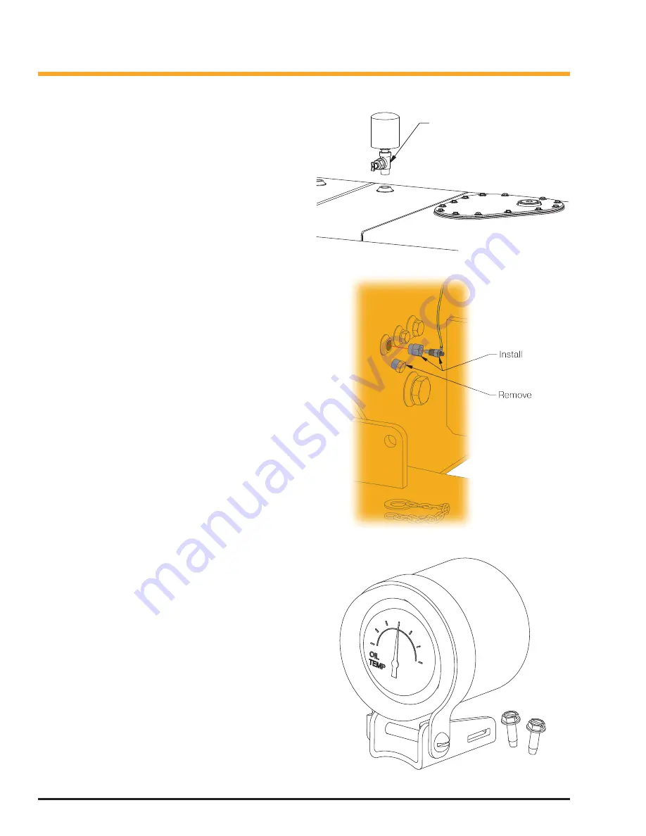
19.  To create negative pressure in the tank:

a.  Relieve pressure in the hydraulic tank by 

opening the petcock

b.  Remove the petcock/air breather assembly. 

See 

Figure 6

.

c.  Attach a vacuum to the open port to create 

negative pressure in the tank. The negative 
pressure will allow the drain plug to be re-
moved without spilling oil.

20.  Remove a 3/4” drain plug from the side of hydrau-

lic tank integral to the chassis. See 

Figure 7

.

21.  Install the bushing and temperature sensor as 

shown in 

Figure 7

.

22.  The temperature sensor has NPTF threads, and 

does not require pipe sealant. Use a light ap-
plication of pipe sealant to the external bushing 
threads. Metal to metal contact is required at the 
threads for proper sensor grounding.

23.  With the temperature sensor securely installed, 

turn off the vacuum, and reinstall the petcock/air 
breather assembly.

24.  Route the yellow wire from the temperature sen-

sor to the terminal block labeled “A” in 

Figure 2

Secure the wire so that it will not be damaged or 
snagged during normal operation or maintenance. 
Strip 5/16” of the insulation from the wire, and 
install at the terminal as shown in 

Figure 2

.

25.  Mount the hydraulic temperature gauge in the cab, 

in a location visible to the operator, where it does 
not obscure any other gauge or control. Use the 
self-tapping screws included in the kit to mount 
the gauge. Use a 11/64” drill for pilot holes.

26.  Route the temperature gauge wire harness back 

to the console or terminal panel assembly. The 
wire harness may be cut to length to simplify 
installation and wire routing.  Make sure not to cut 
the wire harness too short.

27.  Strip 5/16” of the insulation from the wire, and 

install at terminals “A”, “B”, “C”, and “D” as shown 
in 

Figure 2

.

28.  At this time, reconnect the wires that were previ-

ously disconnected from the 2-position terminal 

Figure 6  

Hydraulic Tank Breather

Figure 7  

Sensor Installation

Figure 8  

Hyd Oil Temp Gauge

Summary of Contents for 591004

Page 1: ...al panel assembly Logstack ers 5 These four terminal blocks are labeled A B C and D in Figure 2 To determine which existing terminal blocks to replace for the blocks labeled B and C you may need to temporarily close the battery disconnect switch to test for volt age at the terminal block Make sure to disconnect the battery at the switch again before disconnect ing any wires or removing any termina...

Page 2: ...itor Kit 1 257786 Base Magnet 1 904334 Pad Base 1 591002 Bracket 1 R13811193 Nut Lock 1 16829W Capscrew 1 R13803020 Clip Insulated 1 R13811189 Nut Lock 1 18460W Capscrew 1 590970 Wire Harness 1 591014 Wire Harness 1 239317 Terminal Block 3 591041 Gauge Assembly 1 233244 Machine Screw 6 209505 Fitting 1 ...

Page 3: ...ACK RED YELLOW YELLOW WIRE HARNESS 591014 WIRE HARNESS 590970 WIRE HARNESS ON 591041 BLUE AND GREEN WIRES NOT USED GP S CE LL UL AR RECONNECT EXISTING WIRES HERE RECONNECT EXISTING WIRES HERE RECONNECT EXISTING WIRES HERE B C D E F G Figure 2 Installation Wiring Diagram ...

Page 4: ...ctions to the new terminal blocks yet 7 Terminals E F and G are existing terminal blocks Refer to the electrical schematic for your machine Find the J1939 terminating resistor pig tail It should have wires labeled Green Yellow and Shield on the schematic and look similar to Figure 3 8 Note the terminal numbers and remove the J1939 terminating resistor pigtail Retain pigtail if kit is later removed...

Page 5: ...icle mon itor do not plug in yet to the terminals previously identified as E F and G in Figure 2 The wire harness may be cut to length but do not cut too short 14 Strip 5 16 of the insulation from the individual wires on wire harness 590970 Connect to termi nals E F and G as shown in Figure 2 Do not connect the plug end to the vehicle monitor yet 15 Route wire harness 591014 from the vehicle mon i...

Page 6: ...al contact is required at the threads for proper sensor grounding 23 With the temperature sensor securely installed turn off the vacuum and reinstall the petcock air breather assembly 24 Route the yellow wire from the temperature sen sor to the terminal block labeled A in Figure 2 Secure the wire so that it will not be damaged or snagged during normal operation or maintenance Strip 5 16 of the ins...

Page 7: ...ted may cause equip ment damage Electrical Test 1 Close the battery disconnect switch 2 With the keyswitch in the OFF position a Measure the voltage between terminals C and D The multimeter should display 0 VDC b Measure the voltage between terminals B and C The multimeter should display 24 VDC 3 With the keyswitch in the ON position a Measure the voltage between terminals C and D The multimeter s...

Page 8: ...ext steps 8 If you can see the asset in NearMe or Web Center confirm the following a Vehicle monitor is communicating with the Web Center b Equipment running status indicates that the equipment is running c Battery voltage level displayed for the equip ment matches the expected equipment bat tery voltage level 24 VDC d Confirm that the Map location appears to be correct NOTE The vehicle monitor Lo...

Page 9: ...tered but no Inbound Acknowledgment Alternates from Solid to Fast Blink every 1s Registered and Received Inbound Acknowledgment Solid GPS LED Yellow Definitions Condition LED GPS Off Off GPS On Slow Blinking GPS Time Sync Fast Blinking GPS Fix Solid Table 3 Com 1 LED Definitions Table 4 GPS LED Definitions Figure 9 LED Locations LED Status Charts ...

Page 10: ...10 80 1056 Rev 8 2014 This page is intentionally blank ...

Reviews: