


Description of the data path
OSCAR Technical Manual
V2.4.0
90
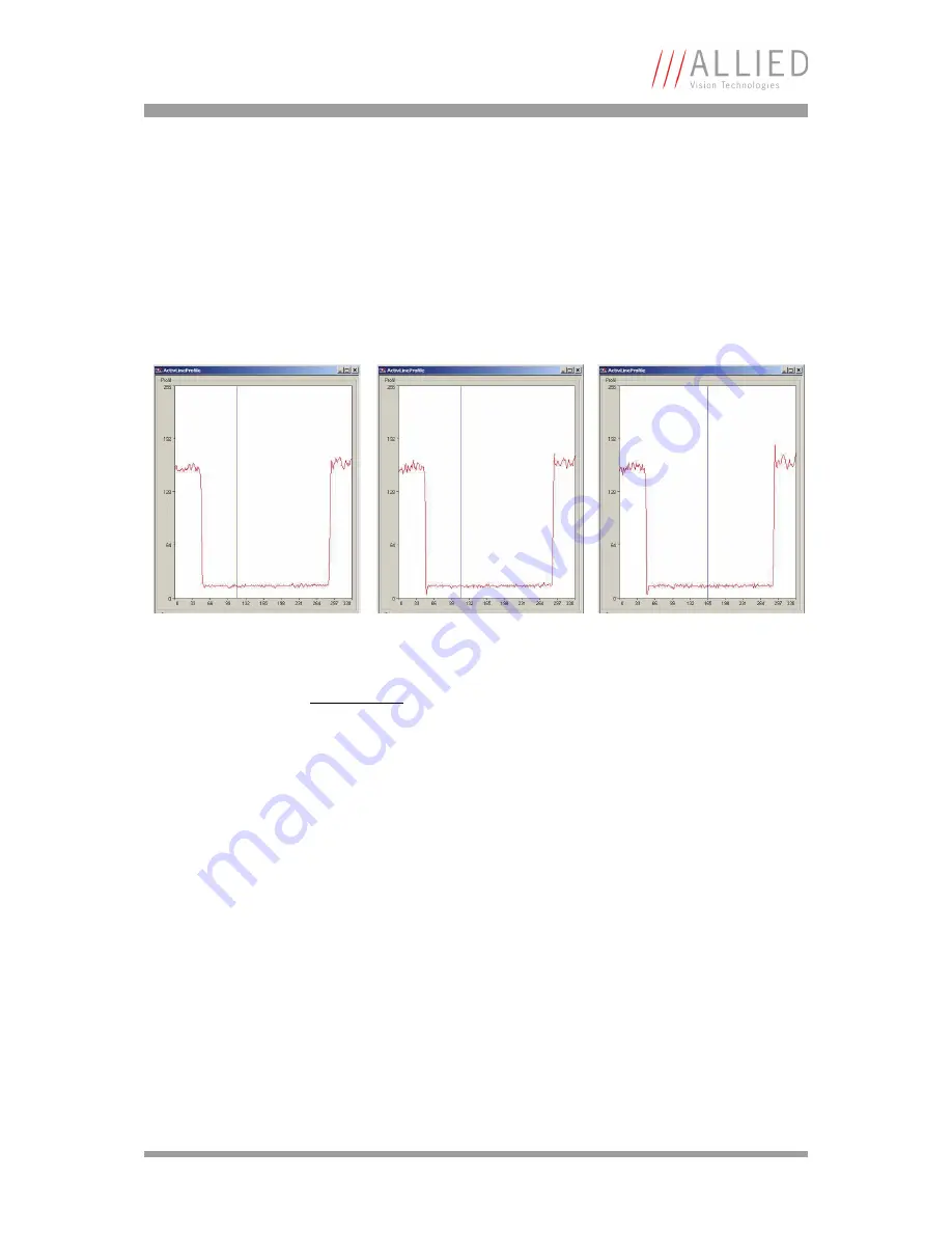
Sharpness
All Oscar models are equipped with a two-step sharpness control, applying a
discreet horizontal high pass in the green channel as shown in the next three
line profiles.
Color interpolation
The color sensors capture the color information via so called primary color
(R-G-B) filters placed over the individual pixels in a
BAYER mosaic
layout.
An effective Bayer
RGB color interpolation already takes place in all Oscar
cameras. Before converting to the YUV format, color correction is done after
BAYER demosaicing.
Color processing can be bypassed by using the so called RAW image transfer.
RAW mode is primarily used to
•
save bandwidth on the IEEE 1394 bus
•
achieve higher frame rates
•
use different BAYER demosaicing algorithms on the PC
Figure 43: Sharpness: left: 0, middle: 1, right: 2
Note
L
Configuration
To configure this feature in feature control register: See
Table 77: Feature control register
on page 169.