background image

Diagnostics and Troubleshooting

20

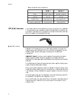
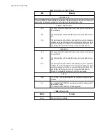
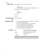
Table 3: Function of AT-TS90TR LEDs

Table 4: Reset Switch

LED

Meaning

NETWORK LOAD

These ten GREEN LEDs approximate the percentage of the switch’s capacity that is in use. The percent-
age of usage increases as a gradient from left to right much like a dynamic bar chart.

10 BASE-T PORT ACTIVITY

LINK

RCV

COL

This steady Green LED indicates that the particular port has a valid link and 
is not partitioned.

This Flashing Green LED indicates that the port is receiving Ethernet pack-
ets.

This Flashing Amber LED will flicker to indicate SQE or collision. Occasional 
collisions are normal in Ethernet networks. Excessive collisions is an indica-
tion of possible segment problems. A constantly illuminated Collision LED 
may indicate that there is a port, cabling, or excessive traffic problem.

100BASE-TX

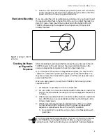
LINK

RCV

COL

This steady Green LED indicates that the particular port has a valid link and 
is not partitioned.

This Flashing Green LED indicates that the port is receiving Ethernet pack-
ets.

This Flashing Amber LED will flicker to indicate SQE or collision. Occasional 
collisions are normal in Ethernet networks. Excessive collisions is an indica-
tion of possible segment problems. A constantly illuminated Collision LED 
may indicate that there is a port, cabling, or excessive traffic problem.
If the port is configured for full duplex, this LED has no meaning.

STATUS

Fault

On – This RED LED will illuminate when the switch detects a general fault 
condition.

Pwr

On – Indicates the AT-TS90TR is receiving power and the voltage is within 
the acceptable range.
Off – Indicates the AT-TS90TR is not receiving power.

Button

Function

Reset

Restarts the system software.

Summary of Contents for TurboStack AT-TS90TR

Page 1: ...TurboStack AT TS90TR Ethernet Switch with Fast Ethernet Access Installation Manual...

Page 2: ...st profits arising out of or related to this manual or the information contained herein even if Allied Telesyn International Corporation has been advised of known or should have known the possibility...

Page 3: ...have been safety tested by UL to Standard UL 1950 CSA to CSA 950 and by TUV to EN60950 ELECTRICAL NOTICES WARNING ELECTRIC SHOCK HAZARD To prevent ELECTRIC shock do not remove cover No user serviceab...

Page 4: ...et sein MONTAGEANWEISUNGEN VORSICHT Die Entl ftungs ffnungen d rfen nicht versperrt sein und m ssen zum K hlen freien Zugang zur Raumluft haben VORSICHT Die Gummif e NICHT ENTFERNEN au er bei Gebrauch...

Page 5: ...en GEVAAR VOOR BLIKSEMINSLAG GEVAAR NIET aan toestellen of KABELS WERKEN bij BLIKSEM WAARSCHUWING HET TOESTEL WORDT UITGESCHAKELD DOOR DE STROOMKABEL TE ONTKOPPELEN OM HET TOESTEL STROOMLOOS TE MAKEN...

Page 6: ...rature ambiante maximum de 40 degr s Celsius POUR TOUS PAYS Installer le mat riel conform ment aux normes lectriques nationales et locales Radioaaltojen h irint EN55022 Luokka A VAROITUS Kotiolosuhte...

Page 7: ...remit e di spina approvata dal paese di destinazione all altra ISTRUZIONI PER IL MONTAGGIO ATTENZIONE le prese d aria non vanno ostruite e devono consentire il libero ricircolo dell aria ambiente per...

Page 8: ...DE CHOQUE CAUSADO POR RAIO PERIGO N O TRABALHE no equipamento ou nos CABOS durante per odos suscet veis de QUEDAS DE RAIO CUIDADO O CABO DE ALIMENTA O UTILIZADO COMO UM DISPOSITIVO DE DESCONEX O PARA...

Page 9: ...20 en un extremo y con un enchufe que est aprobado por el pa s de uso final en el otro INSTRUCCIONES DE MONTAJE ATENCION Las aberturas para ventilaci n no deber n bloquearse y deber n tener acceso lib...

Page 10: ...n anv nds MONTERINGSINSTRUKTIONER VARNING Luftventilerna f r ej blockeras och m ste ha fri tillg ng till omgivande rumsluft f r avsvalning VARNING Ta ej bort gummif tterna fr n produkten om inte ett A...

Page 11: ...boStack Chassis 8 Mounting in a 19 inch rack 9 Stand alone Mounting 9 Cabling 9 Network Connections 10 Complete Installation Instructions 11 TurboStack Chassis Installation 11 Rack Mounting 12 Stand a...

Page 12: ...22 Excessive Flashing of Collision LED 22 Connectivity Problems 23 Technical Support 23 Appendix A Technical Specifications 25 AT TS90TR Specifications 25 Physical 25 Electrical 25 Connector Ports 25...

Page 13: ...TX Ethernet STP UTP ports are available for high speed server or backbone connections with port A one of the 100BASE TX ports also available as an alternative 100 Mbps autosensing full duplex MII Port...

Page 14: ...alone 19 inch rack mount or TurboStack chassis mounting Comprehensive diagnostic LED support 2048 Media Access Control MAC address storage Two modes of switching functionality Cut through Full store a...

Page 15: ...on to the 100BASE TX port A The MII port allows a user to connect a Fast Ethernet transceiver for access to different media such as a fiber optic transmission link The port is autosensing for full or...

Page 16: ...TurboStack chassis Segmented Bus backplane when the AT TS90TR is installed in a TurboStack The Segmented Bus is a seven segment backplane which has been specifically designed for the AT TS90TR switch...

Page 17: ...y Check CRC errors before forwarding a packet 10BASE T Store and forward Store and forward means that your AT TS90TR stores the incoming packet until it has the entire packet and then forwards it Stor...

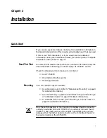
Page 18: ...ton to make sure it contains An AT TS90TR One DB 9 to DB 25 converter Mounting hardware Mounting Your AT TS90TR may be mounted As a stand alone unit Refer to Stand alone Mounting on page 9 for detaile...

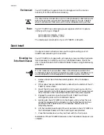
Page 19: ...wer down other units already mounted in the TurboStack chassis during the installation process Your TurboStack units are all designed to be hot swappable to minimize network down time 1 Remove the air...

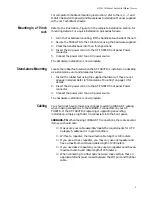
Page 20: ...re if they are not already installed Refer to Stand alone Mounting on page 13 for details 2 Insert the AC power cord into the AT TS90TR front panel Power connector 3 Connect the power cord to an AC po...

Page 21: ...cted to an existing Ethernet network starts working as soon as power is applied System operation is indicated by activity on the front panel LEDs Refer to Checking the Power up Diagnostics Sequence on...

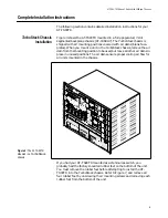
Page 22: ...tack chassis remove the air dam from the mounting position to be used but leave all other air dams in place in unused positions The air dams ensure proper cooling air flow for all units mounted in the...

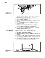
Page 23: ...the installation into the TurboStack Chassis Rack Mounting Installation in a standard rack mount is straightforward 1 Place the AT TS90TR chassis in the cabinet 2 Lift the handles on each side of the...

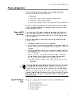
Page 24: ...power up sequence press the reset button You may also remove then reinstall the power cord The unit does not have a power on off switch When you apply power or reset the AT TS90TR the following norma...

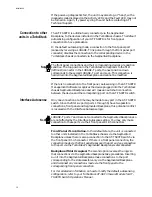
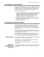
Page 25: ...en the device and the corresponding port on the AT TS90TR switch Interface Autosense Only one connection at a time may be made to any port in the AT TS90TR switch Since the first six ports ports 1 thr...

Page 26: ...has two 100 Mbps Ethernet ports one port is a 100BASE TX port and uses an RJ 45 connector The other 100Mbps Ethernet port Port A as shown in Figure 2 on page 3 has two possible connections and can us...

Page 27: ...eristics are radically different The identification problem is made worse by some suppliers selling voice quality cables as data quality cables If any voice quality cables are used in a 10BASE T netwo...

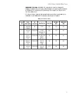
Page 28: ...ecifications and their applicability to 10BASE T and 100BASE TX networks are shown in Table 2 Table 2 Twisted Pair Cable Cable Cat Cable Description AC Character Specification Twist Foot 10BASE T OK 1...

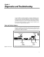
Page 29: ...agement System NMS Status and Activity Indicators As shown in the following illustration the front panel includes LEDs that indicate the status and or activity of various system components They are al...

Page 30: ...on LED may indicate that there is a port cabling or excessive traffic problem 100BASE TX LINK RCV COL This steady Green LED indicates that the particular port has a valid link and is not partitioned T...

Page 31: ...n of Network Load LEDs flash for several seconds indicating the internal diagnostic sequence is running 3 After several seconds the Port Link LEDs and the Network Load LEDs turn off if there are no co...

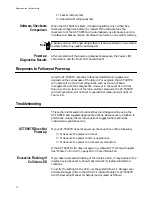
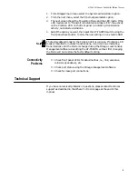
Page 32: ...ailure such as a failure of the main element processor the AT TS90TR will halt execution will not boot to operational mode and will light its Fault LED Troubleshooting This section lists several situa...

Page 33: ...ting in non volatile RAM The factory default mode for the Collision LED is collision If Collision LED mode is modified to indicate transmissions it will continue indicating transmissions until the Mod...

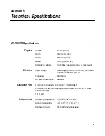
Page 34: ...l Input voltage Auto ranging from 100 to 120VAC 1 5A and from 200 to 240VAC 0 75A Frequency 50 to 60Hz AC power consumption 82 watts Connector Ports 10 RJ45 Ethernet ports 8 10BASE T 2 100 BASE T 1 RS...

Page 35: ...Addresses Management Support Omega Local Console Manager Factory loading into AT TS90TR AT View for AT TS90TR Option AT View for HP OpenView Windows AT TS90TR Option AT View for HP OpenView AT TS90TR...

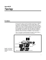
Page 36: ...however for the devices at the maximum distance to detect the collision the diameter of 100BASE TX has to be smaller Figure 11 represents a sample standalone topology All eight 10BASE T ports are ava...

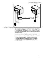
Page 37: ...ink the various workgroups through the switches The advantages of a backbone network topology are The backbone connection uses the high speed 100BASE TX capability of the AT TS90TR thereby increasing...

Page 38: ...g the AT TS90TR in a TurboStack chassis increases overall bandwidth of the TurboStack chassis from 10 Mbps to 80 Mbps while at the same time also providing access to two 100 Mbps backbones The flexibi...

Page 39: ...Uses RJ45 connectors and sometimes 50 pin AMP connectors to a patch panel Runs at 10 MHz 100BASE TX IEEE 802 3 physical layer specifications for 100Mbps Ethernet over various wiring specifications 100...

Page 40: ...ess method employed by IEEE 802 3 LAN transceivers by which multiple stations compete for use of the transmission medium coax cable for data packet transmission and provides for a level of error detec...

Page 41: ...s See Hub Repeater Repeater DIX CONNECTOR See D Sub Connector FOIRL A fiber optic standard that allows up to 1 000 meters 3 280 ft of multimode duplex fiber optic cable in a point to point link HARMON...

Page 42: ...f a pulse transmitted from point A on one pair and validated at point B Point B also transmits a pulse on the second pair to be validated by point A These pulses occur during media idle states in betw...

Page 43: ...f the UTP wiring has RD and RD inadvertently crossed the polarity correction function will sample the signal and electrically swap the wires If the TD and TD wires are crossed the correction would occ...

Page 44: ...not a module among other modules in a department concentrator chassis STRAIGHT THROUGH A type of wiring connection where the pins of one connector connect to the same pins of another connector For ex...

Page 45: ...LDED TWISTED PAIR UTP A cable used in 10BASE T wiring that consists of at least two twisted pairs of 22 to 26 AWG wire The pairs should have at least 3 twists per foot and have an impedance of 100 Lev...

Page 46: ...agnostics _______ Troubleshooting _______ I found the following the most valuable _________________________________________________________________ ____________________________________________________...

Page 47: ...se 32 carrier sense multiple access with collision detect CSMA CD 32 certification 26 checksum comparison test 22 coax segment 32 coaxial cable 32 coaxial cable segment 32 collision presence 32 compat...

Page 48: ...er NIC 16 non volatile memory 22 P patch panel 35 Physical Medium Attachment PMA 35 Physical Signaling PLS 35 polarity correction 35 power up LED sequence 13 21 power up diagnostics 13 21 results 22 s...

Page 49: ...ake City UT Tel 801 350 9130 Fax 801 350 9051 Vienna VA Tel 703 506 0196 Fax 703 506 1986 Chicago IL Tel 708 406 8431 Fax 708 406 8462 Austin TX Tel 512 502 3087 Fax 512 794 9326 Dallas TX Tel 214 446...

Reviews: