


9
Figure 1: Front Panel ............................................................................................................................................................ 18
Figure 2: Back Panel ............................................................................................................................................................ 18
Figure 3: Link/Activity and Duplex Mode LEDs for the 10/100/1000Mbps Copper Ports ..................................................... 26
Figure 4: Link/Activity LEDs on the 1/2.5/5/10Gbps Copper Port......................................................................................... 27
Figure 5: Link/Activity LED for the 1/10Gbps SFP+ Port ...................................................................................................... 28
Figure 6: Switch ID LED ....................................................................................................................................................... 31
Figure 7: Switch ID LED With Low Power Mode Disabled ................................................................................................... 31
Figure 8: Switch ID LED With Low Power Mode Enabled .................................................................................................... 32
Figure 9: GS970EMX/10 Switch Accessory Items................................................................................................................ 44
Figure 10: Installation Options for the GS970EMX/10 Switch .............................................................................................. 45
Figure 11: Switch Installation on a Table.............................................................................................................................. 46
Figure 12: Unsupported Table Installations .......................................................................................................................... 46
Figure 13: Attaching the Bumper Feet.................................................................................................................................. 47
Figure 14: GS970EMX/10 Switch in an Equipment Rack with the RKMT-J05 Brackets Kit ................................................. 50
Figure 15: GS970EMX/10 Switch with RKMT-J05 Cable Trays ........................................................................................... 51
Figure 16: Items in the RKMT-J05 Equipment Rack Brackets Kit ........................................................................................ 52
Figure 17: Placing the GS970EMX/10 Switch Upside Down on a Table..............................................................................53
Figure 18: Removing the Feet from the GS970EMX/10 Switch ........................................................................................... 54
Figure 19: Attaching the RKMT-J05 Handles to the Short Brackets..................................................................................... 54
Figure 20: Attaching the Short RKMT-J05 Brackets to the Long Brackets........................................................................... 55
Figure 21: Attaching the RKMT-J05 Cord Trays to the Long Brackets................................................................................. 56
Figure 22: Attaching the RKMT-J05 Brackets to the Switch................................................................................................. 57
Figure 23: Attaching the GS970EMX/10 Switch to an Equipment Rack............................................................................... 58
Figure 24: BRKT-J23 Bracket Kit.......................................................................................................................................... 60
Figure 25: GS970EMX/10 Switch Wall Installations with Two BRKT-J23 Brackets ............................................................. 60
Figure 26: GS970EMX/10 Switch Wall Installations with Four BRKT-J23 Brackets............................................................. 61
Figure 27: Invalid Wall Installation with Front Panel Facing Down ....................................................................................... 61
Figure 28: Marking the Screw Holes for Two BRKT-J23 Brackets ....................................................................................... 65
Figure 29: Marking the Screw Holes for Four BRKT-J23 Brackets ...................................................................................... 65
Figure 30: Attaching the Bottom BRKT-J23 Brackets to the Wall......................................................................................... 66
Figure 31: Sliding the Switch into the BRKT-J23 Brackets................................................................................................... 67
Figure 32: Attaching the Top BRKT-J23 Brackets to the Wall.............................................................................................. 68
Figure 33: Installing the Power Cord Retaining Clip ............................................................................................................. 70
Figure 34: Connecting the AC Power Cord .......................................................................................................................... 71
Figure 35: Lowering the Power Cord Retaining Clip............................................................................................................. 71
Figure 36: Connecting the Power Cord to an AC Power Source.......................................................................................... 71
Figure 37: Management Cable Included with Switch............................................................................................................ 73
Figure 38: VT-Kit3 Management Cable ................................................................................................................................ 73
Figure 39: Management Workstation, VT-Kit3 Management Cable, and Switch.................................................................. 74
Figure 40: Connecting the Management Cable to the Console Port .................................................................................... 74
Figure 41: User Exec Mode Prompt ..................................................................................................................................... 75
Figure 42: Verifying the Switch ID LED ................................................................................................................................ 76
Figure 43: Installing an SFP+ Transceiver ........................................................................................................................... 80
Figure 44: Removing the Dust Cover from an SFP+ Transceiver ........................................................................................ 81
Figure 45: Positioning the SFP+ Handle in the Upright Position .......................................................................................... 81
Figure 46: Connecting a Fiber Optic Cable to an SFP or SFP+ Transceiver ....................................................................... 82
Figure 47: Installing an SP10TW Cable................................................................................................................................ 83
Figure 48: GS970EMX/10 Switch Dimensions ..................................................................................................................... 90
Figure 49: Pin Layout for the RJ-45 Copper Ports (Front View) ........................................................................................... 96
Figures
Summary of Contents for GS970EMX/10
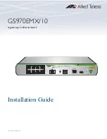
Page 1: ...613 003019 Rev A GS970EMX 10 Gigabit Layer 3 Ethernet Switch Installation Guide...
Page 6: ...6...
Page 10: ...Figures 10...
Page 12: ...Tables 12...
Page 16: ...Preface 16...
Page 36: ...Chapter 1 Overview 36...
Page 48: ...Chapter 2 Beginning the Installation 48...
Page 88: ...Chapter 7 Troubleshooting 88...