Installing your Allied Telesyn AT-BRKT15
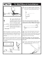
1. Using the bracket as a template, mark the screw holes.
2. Use an awl or other punch to punch pilot holes.
3. Drill the holes.
4. If mounting on wallboard, insert the Bantam plugs into the holes.
Figure 1: Vertical Installation Example
Gently encourage the plugs with a hammer if necessary.
5. Remove the repeater’s bottom corner screws (B) and rubber feet.
6. Mount the repeater in the bracket using the corner screws, but
without the rubber feet.
7. Mount the bracket to the wall using the #8 x 7/8" pan head Phillips
screws (D).
8. Set aside the rubber feet. They are no longer required.
For specific dimensions, please see Figure 2.
Figure 2: Dimensions
These dimensions are subject to change without further notice from ATI.
C
D
B
A
B
D
4.63
0.20
0.37
0.14
3.67
4.63
1.70
6.14
10.40
8.15
(15.60)
(11.76)
(0.94)
(0.36)
(0.51)
(9.32)
(11.76)
(4.32)
(26.42)
(20.70)
2
3


