Allied Telesis 2914 Series Installation And User Manual Download Page 75

Chapter 6: Modifying Advanced Properties

75

Flow Control

The Flow Control feature allows you to control the flow between the 

AT-2914 adapter port and its link partner. You can enable or disable the 

adapter port to process received PAUSE frames and transmit PAUSE 

frames.

To enable or disable the Flow Control feature, do the following:

1. Access the Advanced Properties.

See “Accessing Advanced Properties” on page 71. 

2. Select 

Flow Control 

in the Property box.

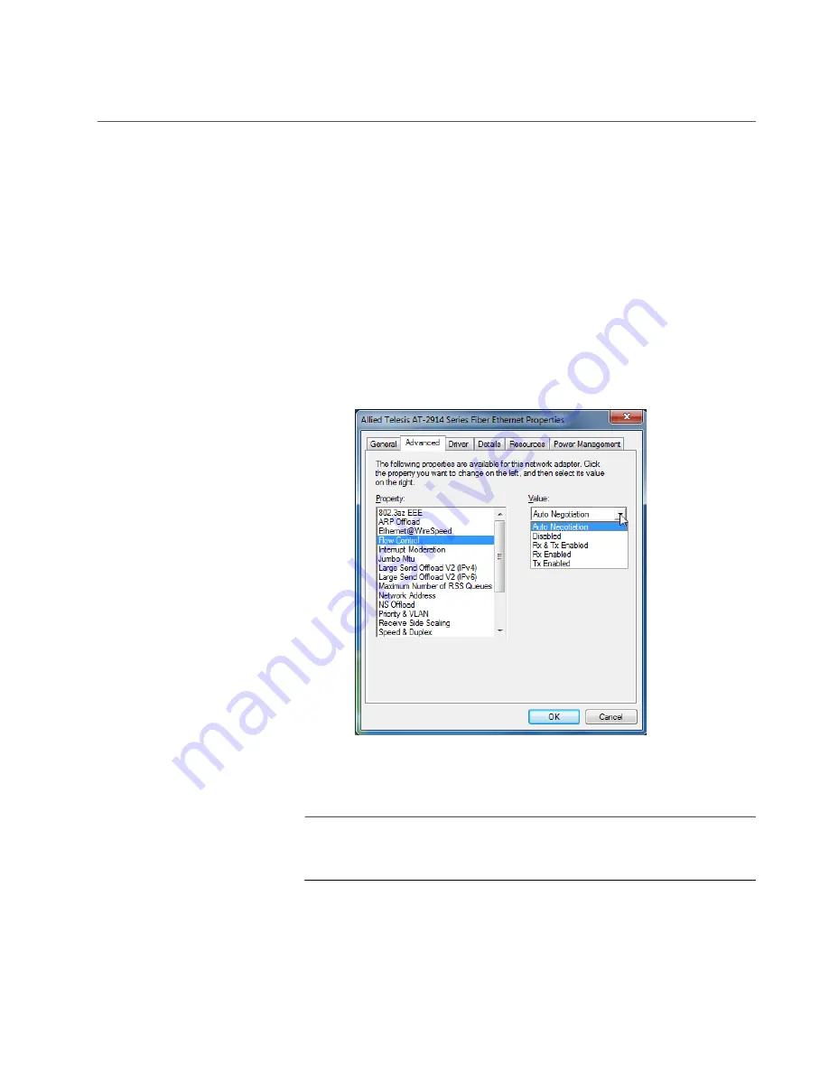
The Flow Control page is displayed as shown in Figure 34.

Figure 34. Flow Control Page

3. Select one of the following options if available:

Note

The options and default setting depend on your operating system 

and the version of the driver that you installed.

Auto Negotiation —

 The setting of the Flow Control property is 

determined during the auto-negotiation process.

Disabled —

 The adapter ignores PAUSE frames.

Summary of Contents for 2914 Series

Page 1: ...613 002358 Rev B 2914 Series Fiber Network Adapters with Wake on LAN WoL AT 2914SX SC AT 2914SX LC AT 2914SP AT 2914GP SP Installation and User s Guide...

Page 2: ...rks or registered trademarks of their respective owners Allied Telesis Inc reserves the right to make changes in specifications and other information contained in this document without prior written n...

Page 3: ...dio frequency energy and if not installed and used in accordance with the instructions may cause harmful interference to radio communications However there is no guarantee that interference will not o...

Page 4: ...g process controls Safety and Electromagnetic Emissions Certificates Standard Compliance CE RoHs compliant European Union RoHS Directive 2011 65 EU of the European Parliament and of the Council of 8 J...

Page 5: ...vailable in a PDF document titled Translated Safety Statements on the Allied Telesis website at www alliedtelesis com support Remarque Les consignes de s curit portant le symbole sont traduites dans p...

Page 6: ...6...

Page 7: ...nstalling the Hardware 29 System Requirements 30 Reviewing Safety Precautions 31 Pre Installation Checklist 33 Replacing the Bracket 34 Installing a Network Adapter 36 Connecting the AT 2914GP PSU Pow...

Page 8: ...erview 66 Configuring VLAN Tagging on Adapter Ports 67 VLAN Tagging Combinations 67 Using VLAN Capable VoIP Phones to Set up VLAN 68 Using AT 2914GP SP to Set up VLAN 68 Non VLAN Application 68 Chapte...

Page 9: ...tic Ports 105 Twisted Pair Ports 107 Testing Network Connectivity 109 Guidelines 109 Windows 109 Linux 110 Appendix A Specifications 111 Physical Specifications 111 Environmental Specifications 111 Po...

Page 10: ...2914 Series Gigabit Ethernet Network Adapters with WoL Installation and User s Guide 10...

Page 11: ...4 Series of Fiber Network Adapters with WoL The network adapters included in this series are AT 2914SX SC AT 2914SX LC AT 2914SP AT 2914GP SP The Preface contains the following sections Safety Symbols...

Page 12: ...tes provide additional information Caution Cautions inform you that performing or omitting a specific action may result in equipment damage or loss of data Warning Warnings inform you that performing...

Page 13: ...handise Authorization RMA and contact Allied Telesis technical experts USA and EMEA phone support Select the phone number that best fits your location and customer type Hardware warranty information L...

Page 14: ...2914 Series Fiber Network Adapters with WoL Installation and User s Guide 14...

Page 15: ...ber Optic Network Adapters with WoL This chapter contains the following sections Description on page 16 The AT 2914GP SP Network Adapter on page 20 Supported Operating Systems on page 24 Accessing Doc...

Page 16: ...receives and wakes up when the computer s MAC address matches one in the magic packet The AT 2914SX SC and AT 2914SX LC models are Gigabit Ethernet network adapters operating at 1000Mbps The AT 2914SP...

Page 17: ...ower supply unit see The AT 2914GP SP Network Adapter on page 20 Duplex SC Fiber Optic Connector The AT 2914SX SC network adapter is equipped with a 1000BASE SX port with a duplex SC connector See Fig...

Page 18: ...plex mode only See Figure 4 Note An SFP transceiver must be purchased separately For a list of supported transceivers see the product s data sheet Figure 4 SFP Slot LED The fiber optic port on the net...

Page 19: ...ort has two LEDs For link states and descriptions see Table 2 LED for Fiber Optic Port LED for Twisted Pair Port Table 2 LED Status for the Twisted Pair Port on AT 2914GP SP LED State Description Top...

Page 20: ...on the adapter to the same network The adapter appears to the PC as a single port network adapter like other 2914 series adapters The data from the copper port and the PC is routed directly to the fi...

Page 21: ...powered off When the AT 2914GP PSU power supply unit is present the AT 2914GP SP adapter uses the power supply unit to provide power to the PD and does not use 12V power from the PCIe slot Console Po...

Page 22: ...sed to add VLAN QoS Priority tags to the phone and or PC data traffic To add VLAN QoS Priority tags see Chapter 4 Configuring the VLAN and Priority on page 55 To use the AT 2914GP SP adapter as a brid...

Page 23: ...ventions The conventions are defined in Table 3 Table 3 2914 Series Model Naming Conventions Convention Definition 1 Indicates the product name 2 Identifies the type of the port The following is a lis...

Page 24: ...Linux 2 6 3 x The 2914 series network adapter that is installed on Linux systems uses Linux inbox driver software to operate so that you do not need to install driver software for Linux systems A driv...

Page 25: ...e following 1 Open a web browser such as Internet Explorer or FireFox on your system and enter the following http www alliedtelesis com The Allied Telesis home page is displayed 2 Enter 2914 in the se...

Page 26: ...Standard profile bracket The standard profile bracket is longer than the low profile bracket The 2914 series network adapters are shipped with a low profile bracket attached Note The driver software...

Page 27: ...are covered under limited warranties All Allied Telesis warranties are subject to and provided only on the terms and conditions set out in the Allied Telesis For more information visit the Allied Tel...

Page 28: ...2914 Series Fiber Network Adapters with WoL Installation and User s Guide 28...

Page 29: ...ments on page 30 Reviewing Safety Precautions on page 31 Pre Installation Checklist on page 33 Replacing the Bracket on page 34 Installing a Network Adapter on page 36 Connecting the AT 2914GP PSU Pow...

Page 30: ...e 30 System Requirements Before installing the 2914 series network adapter make sure your system meets the requirements listed below PC with one of the following operating systems Windows 10 in 64 bit...

Page 31: ...ser beam L2 Warning The fiber optic ports contain a Class 1 laser device When the ports are disconnected always cover them with the provided plug Exposed ports may cause skin or eye damage L4 Warning...

Page 32: ...our hands and wrists Make sure to use only insulated or nonconducting tools Verify that the system is powered OFF and unplugged before accessing internal components Installation or removal of modules...

Page 33: ...ord the path to where the driver file resides on your system 4 If your system is active shut it down 5 When system shutdown is complete power OFF and unplug your system 6 Holding the adapter card by t...

Page 34: ...racket from the network adapter and replace it with the standard bracket You can also use this procedure to remove the standard bracket and replace it with the low profile bracket To replace the low p...

Page 35: ...Chapter 2 Installing the Hardware 35 Figure 11 Installing the Standard Bracket...

Page 36: ...n followed Warning The module is being installed in a system that operates with voltages that can be lethal Before you remove the cover of your system you must observe the following precautions to pro...

Page 37: ...d it for future use See Figure 13 Figure 13 Removing the Faceplate From PCIe Slot 4 Remove the network adapter from the shipping package and store the packaging material in a safe location 5 Applying...

Page 38: ...the system or the adapter If the adapter resists seating remove it from the system realign it and try again E47 6 Secure the network adapter to the chassis with a Phillips head screw not provided as s...

Page 39: ...Chapter 2 Installing the Hardware 39 Next connect the network cables See Connecting the Network Cables on page 41...

Page 40: ...r rail It is typically 10 15W however verify your system s specifications and derate by 20 for planning purposes To connect the AT 2914GP PSU power supply unit to the AT 2914GP SP adapter perform the...

Page 41: ...Ethernet network port After the system is connected to the network and power is supplied the network adapter attempts to negotiate duplex and flow control via the auto negotiation protocol If the link...

Page 42: ...on as follow With a Gigabit SFP the network adapter attempts to negotiate duplex and flow control via the Clause 37 Auto Negotiation protocol If the link partner does not support Auto negotiation the...

Page 43: ...eries network adapter onto your Windows platform It contains the following topics Overview on page 44 Downloading the Driver Software on page 45 Accessing the Device Manager on page 48 Installing the...

Page 44: ...a default Broadcom driver If your system has another Allied Telesis network adapter previously installed the system installs the Allied Telesis driver that resides in your system instead of the defaul...

Page 45: ...e from the Allied Telesis website To download the driver software do the following 1 Open a web browser such as Internet Explorer or FireFox on your system and enter the following http www alliedteles...

Page 46: ...fill the fields and click Request Guest Access You will receive a guest login account and password via email 3 Click Download Center The Login page is displayed See Figure 18 Figure 18 Login Page 4 En...

Page 47: ...9 on page 46 6 Enter 2914 in the search box and click Search The link to the driver for the 2914 products is listed 7 Select the link 8 Save the zip folder onto your system 9 Right click the zip folde...

Page 48: ...2914 series network adapter you must first access Device Manager To access the Device Manager on your Windows 10 operating system perform the following 1 Right click the bottom left corner The Quick A...

Page 49: ...ce Manager window double click Network Adapters to expand the field 3 Right click Allied Telesis AT 2914 Series Fiber Ethernet Note The Device Manager may list your adapter as a Broadcom device or All...

Page 50: ...elect Browse my computer for driver software The Update Driver Software window prompts you to enter the location of the driver folder See Figure 23 as an example Figure 23 Update Driver Software Windo...

Page 51: ...r 3 Installing the Driver Software 51 The confirmation message shown in Figure 24 appears when the driver software is successfully updated Figure 24 Update Driver Software Window Confirmation 8 Click...

Page 52: ...software you use the same procedure for installing the driver software for the first time The only difference between updating and installing the driver software is the name of your adapter that Devi...

Page 53: ...the Microsoft website Installing the Driver Silently To install the driver silently perform the following instructions 1 Create a folder in your Windows system 2 Download driver software for the AT 29...

Page 54: ...dialog boxes and other user intervention requests The driver is installed silently Viewing Supported DPInst Options You can display help information about the dpinst command line options View all sup...

Page 55: ...network adapter and change the VLAN and priority settings It contains the following topics Overview on page 56 Accessing the CLI on the AT 2914GP SP Network Adapter on page 57 Configuring the VLAN an...

Page 56: ...stalled you can access the CLI to modify the VLAN and priority settings using a terminal emulator program such as Putty or TeraTerm on the management PC Figure 25 Accessing the CLI on the Adapter thro...

Page 57: ...2914GP SP adapter is installed on Accessing the CLI on the Adapter for the First Time To connect the AT 2914GP SP adapter to a PC perform the following procedures 1 Connect the USB A connector of the...

Page 58: ...y To download and install the serial port driver to the management laptop or PC perform the following 1 Go to SILISON LABS s website www silabs com products development tools software usb to uart brid...

Page 59: ...tacle on the AT 2914GP SP adapter 3 Start the terminal emulator program with the COM number that you noted from Device Manager 4 Configure the terminal emulator program as follows Baud rate 115200 Dat...

Page 60: ...ns are enabled or disabled The default is disabled PoE VID Displays the VLAN ID for the PoE copper port The default is 0 The range is 0 to 4095 PoE QoS Displays QoS priority level for the PoE copper p...

Page 61: ...t is displayed to indicate changes have been made but not yet applied 3 Enter 7 at the Console prompt to apply the change 7 VLAN Configuration Applied prompt is displayed 4 Press Enter to continue Dis...

Page 62: ...settings prompt is displayed to indicate changes have been made but not yet applied 3 Enter 7 at the Console prompt to apply the new setting 7 VLAN Configuration Applied prompt is displayed 4 Press En...

Page 63: ...nsole prompt to apply the new setting 7 VLAN Configuration Applied prompt is displayed 4 Press Enter to continue Changing the QoS Priority Level for the PC Traffic You can specify the QoS priority lev...

Page 64: ...2914 Series Fiber Network Adapters with WoL Installation and User s Guide 64...

Page 65: ...a VoIP Phone System This chapter describes how to configure a VoIP phone system using the AT 2914GP SP network adapter It contains the following topics Overview on page 66 Configuring VLAN Tagging on...

Page 66: ...se voice traffic must have higher priority over other types of traffic When VLAN s are enabled and configured incoming traffic on the fiber link are routed to the copper port or the PC depending on th...

Page 67: ...this example voice frames belong to the VLAN 150 and data frames belong to the VLAN 10 except Config 3 Figure 29 VoIP Phone Tagging Example Table 5 shows VLAN tagging combinations Table 5 VLAN Taggin...

Page 68: ...nced Properties however when voice frames are tagged at the VoIP phone do not enable VLAN via the AT 2914GP SP adapter s CLI Using AT 2914GP SP to Set VLAN Config 2 is a configuration when a VoIP phon...

Page 69: ...n on page 77 Jumbo Mtu on page 78 Large Send Offload v2 IPv4 on page 79 Large Send Offload v2 IPv6 on page 80 Maximum Number of RSS Queues on page 81 Network Address on page 83 NS Offload on page 85 P...

Page 70: ...access the advanced properties access Device Manager then go to each advanced property page Guidelines Here are the guidelines to modifying the advanced properties To change the advanced property sett...

Page 71: ...ter and select a feature you want to change its setting 1 Access Device Manager See Accessing the Device Manager on page 48 2 In the Device Manager window double click Allied Telesis AT 2914 Series Fi...

Page 72: ...nergy usage of the interface over Ethernet Note The setting is always disabled on the 2914 series adapter To view the 802 3az EEE feature do the following 1 Access the Advanced Properties See Accessin...

Page 73: ...AC address To enable or disable the ARP Offload feature do the following 1 Access the Advanced Properties See Accessing Advanced Properties on page 71 2 Select ARP Offload in the Property box The ARP...

Page 74: ...hrough an impaired copper cable Note The setting is always disabled on the 2914 series adapter To view the Ethernet WireSpeed setting do the following 1 Access the Advanced Properties See Accessing Ad...

Page 75: ...ing 1 Access the Advanced Properties See Accessing Advanced Properties on page 71 2 Select Flow Control in the Property box The Flow Control page is displayed as shown in Figure 34 Figure 34 Flow Cont...

Page 76: ...76 Tx Rx Enabled The adapter processes ingress PAUSE frames and transmits PAUSE frames Rx Enabled The adapter processes ingress PAUSE frames but does not transmit PAUSE frames Tx Enabled The adapter...

Page 77: ...the latency may increase To enable or disable the Interrupt Moderation feature do the following 1 Access the Advanced Properties See Accessing Advanced Properties on page 71 2 Select Interrupt Modera...

Page 78: ...frame size is specified however the network must be capable of supporting the oversized Ethernet frames To change the Jumbo Mtu setting do the following 1 Access the Advanced Properties See Accessing...

Page 79: ...feature if both features are enabled To enable or disable the Large Send Offload v2 IPv4 feature do the following 1 Access the Advanced Properties See Accessing Advanced Properties on page 71 2 Selec...

Page 80: ...e Large Send Offload v2 IPv6 feature do the following 1 Access the Advanced Properties See Accessing Advanced Properties on page 71 2 Select Large Send Offload v2 IPv6 in the Property box The Large Se...

Page 81: ...m number of RSS Queues do the following 1 Access the Advanced Properties See Accessing Advanced Properties on page 71 2 Select Maximum Number of RSS Queues in the Property box The Maximum Number of RS...

Page 82: ...Adapters with WoL Installation and User s Guide 82 RSS 4 Queues The system allocates up to four RSS queues RSS 1 Queue The system allocates up to one RSS queue RSS 2 Queue The system allocates up to...

Page 83: ...administered address Caution A locally administered address overrides the original MAC address stored in the hardware When you change the MAC address be sure to assign a unique MAC address E81 To ass...

Page 84: ...red address is assigned Here are guidelines to assigning a locally administered address The address must be unique The address consists of a 12 digit hexadecimal number for example 000C46005501 The ra...

Page 85: ...feature do the following 1 Access the Advanced Properties See Accessing Advanced Properties on page 71 2 Select NS Offload in the Property box The NS Offload page is displayed as shown in Figure 41 Fi...

Page 86: ...s and receives QoS tagged frames with VLAN Enabled the adapter sends and receives VLAN tagged frames To assign a VLAN ID to the adapter see VLAN ID on page 95 Note The Priority VLAN should always be d...

Page 87: ...gged frames This is the default setting Priority VLAN Disabled The adapter does not send and ignores QoS and VLAN tagged frames Note Select this option when adding VLAN tags via the AT 2914GP SP adapt...

Page 88: ...ltiple CPU s in a multiprocessor system To enable or disable the Receive Side Scaling feature do the following 1 Access the Advanced Properties See Accessing Advanced Properties on page 71 2 Select Re...

Page 89: ...dapters with a Gigabit SFP transceiver attempt to negotiate duplex and flow control If the link partner does not support Auto negotiation the network adapter bypasses the process and attempts to estab...

Page 90: ...2914 Series Fiber Network Adapters with WoL Installation and User s Guide 90 Figure 44 Speed Duplex Page 3 Click OK...

Page 91: ...ess the Device Manager on your operating system See Accessing Advanced Properties on page 71 2 Select TCP UDP Checksum Offload IPv4 in the Property box The TCP UDP Checksum Offload IPv4 page is displa...

Page 92: ...WoL Installation and User s Guide 92 Rx Enabled Enables the TCP UDP Checksum Offload IPv4 function only for receiving IPv4 packets Tx Enabled Enables the TCP UDP Checksum Offload IPv4 function only f...

Page 93: ...1 Access the Device Manager on your operating system See Accessing Advanced Properties on page 71 2 Select TCP UDP Checksum Offload IPv6 in the Property box The TCP UDP Checksum Offload IPv6 page is d...

Page 94: ...WoL Installation and User s Guide 94 Rx Enabled Enables the TCP UDP Checksum Offload IPv6 function only for receiving IPv6 packets Tx Enabled Enables the TCP UDP Checksum Offload IPv6 function only f...

Page 95: ...me in the VLAN tag before transmitting the frame To change the VLAN ID value do the following 1 Access the Advanced Properties See Accessing Advanced Properties on page 71 2 Select VLAN ID in the Prop...

Page 96: ...re do the following 1 Access the Advanced Properties See Accessing Advanced Properties on page 71 2 Select Wake on Magic Packet in the Property box The Wake on Magic Packet page is displayed as shown...

Page 97: ...re do the following 1 Access the Advanced Properties See Accessing Advanced Properties on page 71 2 Select Wake on Pattern Match in the Property box The Wake on Pattern Match page is displayed as show...

Page 98: ...your network To view this setting do the following 1 Access the Advanced Properties See Accessing Advanced Properties on page 71 2 Select WOL Speed in the Property box The WOL Speed page is displayed...

Page 99: ...ribes how to uninstall the driver software for the 2914 series network adapter This chapter contains the following topics Overview on page 100 Uninstalling the Driver Software Using Device Manager on...

Page 100: ...the silent installation method you can also uninstall driver software in two ways Uninstalling the Driver Software Using Device Manager on page 101 Uninstalling the Driver Software Silently on page 10...

Page 101: ...nager See Accessing the Device Manager on page 48 3 In the Device Manager window expand the Network Adapters folder 4 Right click the Allied Telesis AT 2914 Series Fiber Ethernet The shortcut menu app...

Page 102: ...ver without user intervention perform the following steps 1 Open a command prompt window with administrator privileges 2 Change the directory to the folder where the dpinst utility and the driver file...

Page 103: ...s chapter describes troubleshooting procedures It contains the following sections Checking the Port LED on the Adapter on page 104 Fiber Optic Ports on page 105 Twisted Pair Ports on page 107 Testing...

Page 104: ...Driver Software on page 43 Table 6 describes the link status that LED s indicate LEDs on AT 2914SGP SP The twisted pair port has two LEDs For link states and descriptions see Table 7 Table 6 LED Statu...

Page 105: ...ink partner If you are using Bi Di optical transceiver verify the wavelengths are reversed The TX port of the fiber connector on the 2914 series network adapter has the same wavelength as the RX port...

Page 106: ...transceiver that transmits and receives at 1310nm and 1550nm respectively has to be connected to a transceiver that transmits and receives at 1550nm and 1310nm respectively Two BiDi transceivers will...

Page 107: ...er Try connecting another PoE device to the network adapter Try replacing the twisted pair cable Problem 2 The network adapter is not providing power from the PCIe connector to a powered device on the...

Page 108: ...necting another PoE device to the RJ 45 port on the network adapter Try replacing the twisted pair cable Problem 3 The twisted pair port on the network adapter is usable to establish a link to a non P...

Page 109: ...he adapter must be set to Auto Negotiation The switch may work at Auto Negotiation or may need to be set to 100Mbps with the full duplex mode depending on the switch Windows To test the network connec...

Page 110: ...t interface is up and running run ifconfig to check the status of the Ethernet interface In addition you can use the netstat i command to check the statistics on the Ethernet interface Consult the man...

Page 111: ...ft Power Specifications Table 8 Product Dimensions and Weight Model Dimensions Without a Bracket Weight Without a Bracket AT 2914SX C AT 2914SX LC AT 2914SP 87 6mm x 68 9mm 3 5in x 2 7in 40g 1 4oz AT...

Page 112: ...C network adapter Output Optical Power 9 5 Min 4 Max dBM Optical Sensitivity 20 Typ 17 Max dBM Maximum Input Power 3 dBm min Center Wavelength 850 nm Here are the operating specifications for the dupl...

Page 113: ...Table 10 lists the pin signals at 10 100Mbps Table 11 lists the pin signals at 1000Mbps Table 10 Pin Signals at 10 100Mbps on the RJ 45 Twisted Pair Port Pin MDI Signal MDI X Signal 1 TX RX 2 TX RX 3...

Page 114: ...ies Fiber Network Adapters with WoL Installation and User s Guide 114 4 3 TX and RX 5 3 TX and RX 6 2 TX and RX 7 4 TX and RX 8 4 TX and RX Table 11 Pin Signals at 1000Mbps on the Twisted Pair Port Co...

Reviews: