


2914 Series Fiber Network Adapters with WoL Installation and User’s Guide
104
Checking the Port LED on the Adapter
This section describes the states of the LEDs.
LED on
AT-2914SX/SC
and
AT-2914SX/LC
The 2914 series network adapter except the AT-2914GP/SP model comes
with one LED. The LED indicates the link and activity status for the port.
Note
Before the port LED can provide troubleshooting information, the
driver software for your particular operating system must be installed
and the adapter must be connected to the network. See Chapter 3,
“Installing the Driver Software” on page 43.
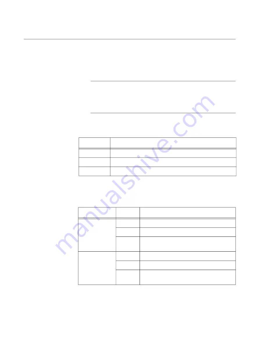
Table 6 describes the link status that LED’s indicate.
LEDs on
AT-2914SGP/SP
The twisted pair port has two LEDs. For link states and descriptions, see
Table 6. LED Status
State
Description
On
Valid link.
Off
No link.
Flashing
The port is receiving or transmitting network packets
Table 7. LED Status for the Twisted Pair Port on AT-2914GP/SP
LED
State
Description
Top-Left LED
(For Twisted
Pair Port)
On
Valid link on the twisted pair port
Off
No link on the twisted pair port
Flashing The twisted pair port is receiving or
transmitting network packets.
Top-right LED
(For Fiber Port)
On
Valid link on the fiber optic port
Off
No link on the fiber optic port
Flashing The fiber optic port is receiving or
transmitting network packets.
Summary of Contents for 2914 Series
Page 6: ...6...
Page 10: ...2914 Series Gigabit Ethernet Network Adapters with WoL Installation and User s Guide 10...
Page 14: ...2914 Series Fiber Network Adapters with WoL Installation and User s Guide 14...
Page 28: ...2914 Series Fiber Network Adapters with WoL Installation and User s Guide 28...
Page 35: ...Chapter 2 Installing the Hardware 35 Figure 11 Installing the Standard Bracket...
Page 64: ...2914 Series Fiber Network Adapters with WoL Installation and User s Guide 64...


