Installation
11
F232160
© Copyright, Alliance Laundry Systems LLC – DO NOT COPY or TRANSMIT
Machine Foundation
A satisfactory foundation and proper installation are
absolutely necessary for the UW50 due to its high
extract speed. Eight 3/4 inch bolts, 8 inches long, are
furnished with each machine and should be imbedded
in a reinforced concrete floor which is a minimum of
12 inches thick. The threaded end of the bolts should
extend about 2 inches above the surface. Refer to
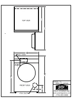
Figure 3
. The location of these bolts is shown in
Figure 4
. Set machine over bolts and shim the machine
so that it sits level; then grout between the floor and
the base of the machine, leaving a small opening for
water drainage at the rear of the machine. After grout
has cured, place lockwashers and nuts on bolts and
tighten securely. DO NOT DISTORT MACHINE BY
BOLTING DOWN ON AN UNEVEN FLOOR
SURFACE. It will be necessary to retighten the bolts
after the machine has run for a short period of time
under load.
If the existing floor is not reinforced concrete a
minimum of 12 inches thick over solid base, it will be
necessary to cut a hole through existing concrete floor
approximately 5 feet square and excavate to a depth of
36 inches from top of existing floor. Refill with
24 inches of WELL compacted clean fill dirt topped
with 12 inches of good concrete reinforced with a
reinforcing wire, and bond existing floor at the sides,
front and back. A bolt locator fixture, made of
reinforcing rod which may be imbedded in the
concrete, is available as an option.
NOTE: Locate bolts and grout as stated above.
Failure to follow these instructions may void the
warranty. THIS MACHINE SHOULD NOT BE
INSTALLED ON A WOODEN FLOOR OR
ABOVE GROUND LEVEL.
Figure 3
Figure 4
PHM178N
NOTE: Existing floor must be a minimum of 12 inches
thick.
1
Machine Base
2
Piece of Angle Welded to Bolt to Prevent
Turning
3
Grouting – 1/2 in. Thick
4
3/4 in.-10 x 8 in. Bolt
5
Conical hole drilled or chiseled into existing
floor. Fill with “Sulfaset” bolt anchor or
equivalent.
PHM191N
0.75 in.
(19 mm)
2 in.
(51 mm)
8 in.
(203 mm)
4
1
TYPICAL METHOD OF MOUNTING USING
INDIVIDUAL MOUNTING BOLTS
2
5
3
MOUNTING BOLT LAYOUT
36 in.
(914 mm)
9
in.
(229 mm)
0.75 in.
(19 mm)
1.25 in.
(32 mm)
0.75 in.
(19 mm)
31.62
in
.
(803 mm)
35.62 in.
(905 mm)
2 in.
(51 mm)
2 in.
(51 mm)
0.75 in.
(19 mm)
39.25 in.
(997 mm)
34.12 in.
(867 mm)
44.81 in.
(1138 mm)
34.56 in.
(878 mm)
10.75 in.
(273 mm)
10.69 in.
(271 mm)
4.81 in.
(122 mm)
FRONT


