background image

37987

39

Section 5 Service Procedures

To reduce the risk of electric shock, fire, explosion, serious injury or death:
• Disconnect electric power to the washer before servicing.
• Never start the washer with any guards/panels removed.
• Whenever ground wires are removed during servicing, these ground wires must be 

reconnected to ensure that the washer is properly grounded.

W003

WARNING

© Copyright, Alliance Laundry Systems LLC – DO NOT COPY or TRANSMIT

37. WASHTUB AND CLOTHES GUARD

a. Open loading door.
b. Remove agitator by placing two agitator hooks, 

No. 254P4P, under bottom edge of agitator. 
Refer to Figure 12.

IMPORTANT: Hooks should be positioned 180 
degrees of each other, and must be placed under 
agitator vane for greater stability. If hooks are 
placed between vane area, agitator damage may 
occur.

c. Using a rocking motion (back and forth) 

carefully lift agitator off drive bell.

d. Hinge cabinet top or remove. Refer to 

Paragraph 34.

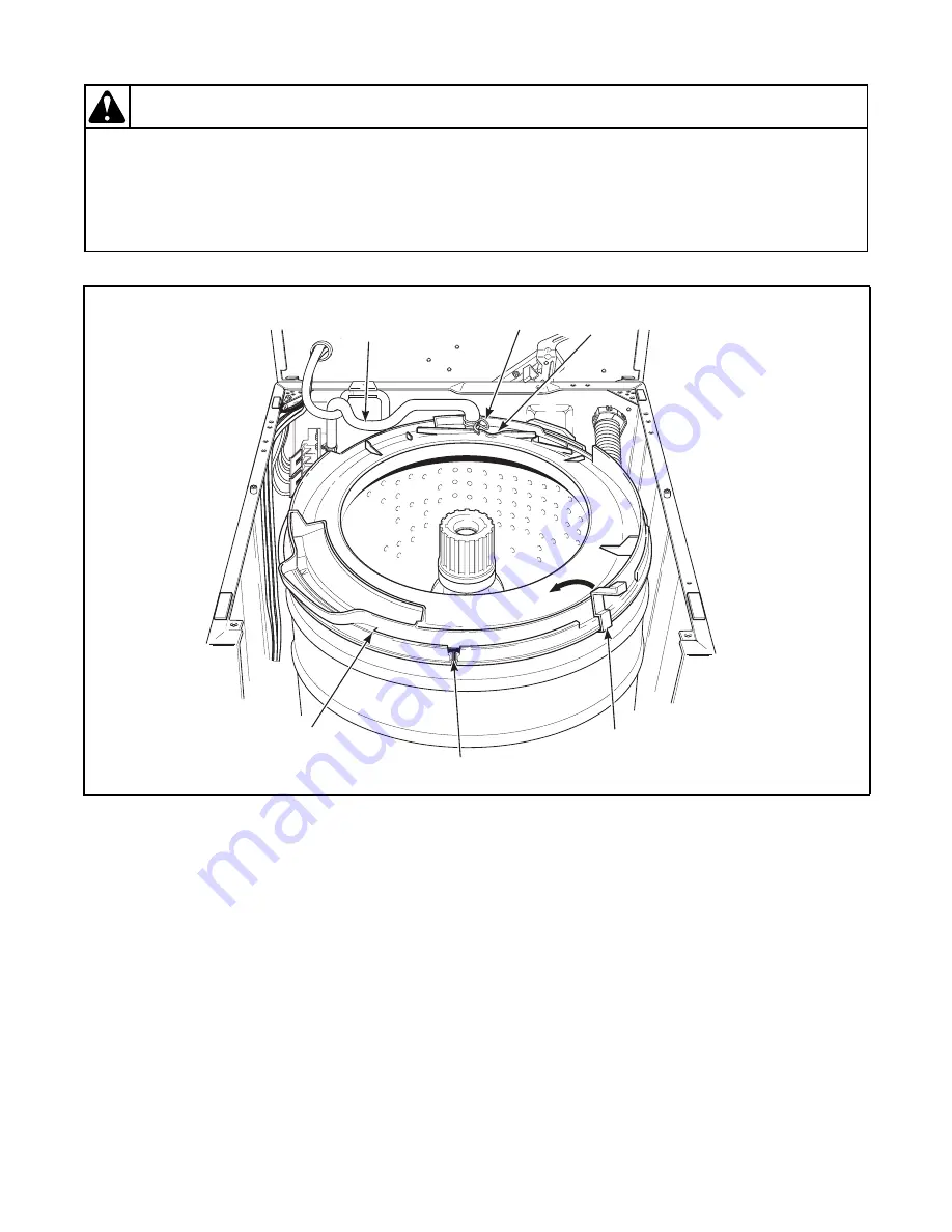
e. Loosen hose clamp and remove filler hose from 

outer tub cover. Refer to Figure 32.

NOTE: When installing filler hose, white line on 
hose must be aligned with line located on top side of 
outer tub cover. Refer to Figure 32
.

f. There are eight tub cover hold-down tabs which 

snap over outer tub flange. Using special tub 
cover tool, Part No. 273P4, insert two prongs of 
tool underneath each side of tandem tabs. Refer 
to Figure 32. Tilt tool toward center of tub 
cover and at same time lift upward on cover to 
unsnap hold-down tabs from outer tub flange. 
One by one, disengage each of the eight hold-
down tabs from outer tub flange and remove 
cover.

Figure 32

W

3

51

S

E

3

A

Line On

Cover

Ho

s

e

Clamp

Filler
Ho

s

e

Hold-Down

Tab

s

Outer

Tub Cover

27

3

P4

Tub Cover

Tool

Summary of Contents for ZWC372-3059

Page 1: ...www comlaundry com Service Part No 37987R1 April 2006 Home Automatic Washers CE Approved Models Refer to Page 5 for Model Numbers ...

Page 2: ......

Page 3: ...ty Check 15 18 Power Cord to Control Hood Rear Panel Control Hood Rear Panel to Control Hood Mounting Bracket Pressure Switch Mounting Bracket and Ground Tab on Graphics Panel 16 19 Control Hood Wire Harness to Top Left Rear Corner Gusset of Cabinet 17 20 Wire Harness to Motor 18 Section 5 Service Procedures 21 Control Hood Assembly 20 22 Timer 20 23 Temperature Switch 21 24 Pressure Switch 23 25 ...

Page 4: ...2 37987 Copyright Alliance Laundry Systems LLC DO NOT COPY or TRANSMIT Notes ...

Page 5: ...ons IMPORTANT The word IMPORTANT is used to inform the reader of specific procedures where minor machine damage will occur if the procedure is not followed NOTE The word NOTE is used to communicate installation operation maintenance or servicing information that is important but not hazard related In the interest of safety some general precautions relating to the operation of this machine follow F...

Page 6: ...lliance Laundry Systems also recommends contacting an authorized technician and using authorized factory parts To reduce the risk of electric shock fire explosion serious injury or death Disconnect electric power to the washer before servicing Never start the washer with any guards panels removed Whenever ground wires are removed during servicing these ground wires must be reconnected to ensure th...

Page 7: ...ion Model Identification Information in this manual is applicable to these washer models Washer Model One Speed Motor Porcelain Washtub Cu Ft Stainless Steel Washtub Cu Ft AWC393 23059 X 3 0 NWC393 3059 X 3 0 ZWC372 3059 X 3 0 ZWC373 3059 X 3 0 Add Letter To Designate Color L Almond W White ...

Page 8: ...the machine was purchased or contact Alliance Laundry Systems at 920 748 3950 for the name and address of the nearest authorized parts distributor For technical assistance call 920 748 3121 Nameplate Location When calling or writing about your product be sure to mention model and serial numbers Model and serial numbers are located on nameplate s as shown C H Model and Serial No W292PE3A ...

Page 9: ...ve hot water mixing valve solenoid Test solenoid and replace if inoperative Inoperative timer Test timer and replace if inoperative Inoperative temperature switch Test switch and replace if inoperative Inoperative pressure switch Test switch and replace if inoperative Clogged pressure hose Remove and clean or replace hose Broken loose or incorrect wiring Refer to appropriate wiring diagram POSSIBL...

Page 10: ...mature spring Disassembly valve and replace spring or replace complete valve A siphoning action started in washer will cause water to be siphoned from washer during cycle due to end of drain hose being lower than cabinet top of washer Drain hose fits tight in standpipe or drain Install No 562P3 Siphon Break Kit Provide an air gap around drain hose and drain receptacle Water in pressure hose Blow a...

Page 11: ...cycled Wait two or three minutes for overload protector to reset If protector cycles repeatedly refer to Paragraph 9 Bind in upper or lower motor bearing Remove belts and determine if motor shaft will spin Replace motor if shaft is locked up Broken loose or incorrect wiring Refer to appropriate wiring diagram Power cord is miswired Refer to appropriate wiring diagram for correct wiring POSSIBLE CA...

Page 12: ...noperative Shorted or incorrect wiring Refer to appropriate wiring diagram Inoperative transmission assembly Repair or replace transmission assembly POSSIBLE CAUSE TO CORRECT Belt is tacky and does not allow proper slip Check belt and replace if defective Belt tension is too great and does not allow proper slip Make sure idler spring is properly connected Inoperative timer Test timer and replace i...

Page 13: ...elt Washer has gone out of balance Open loading door to reset out of balance switch Rearrange load in washtub Motor will not run Check motor and replace if inoperative Sheared motor pulley roll pin Remove drive motor and replace roll pin and any other damaged parts Motor overload protector has cycled Wait two or three minutes for overload protector to reset If protector cycles repeatedly refer to ...

Page 14: ...roken loose or incorrect wiring Refer to appropriate wiring diagram Motor overload protector has cycled Wait two or three minutes for overload protector to reset If protector cycles repeatedly refer to Paragraph 9 Motor switch functions inoperative Check motor switch and replace if inoperative Brake transmission or motor have locked up and will not turn Check that all these components are able to ...

Page 15: ...t properly leveled Adjust leveling legs Washer is installed on weak spongy carpeted or built up floor Relocate washer or support floor to eliminate weak or spongy condition Incorrect or loose cabinet screws Replace with correct screws or tighten Base damaged washer was dropped Replace base assembly Balance ring not positioned properly on transmission assembly Refer to Paragraph 44 Lubricant on piv...

Page 16: ...14 37987 Section 3 Troubleshooting Copyright Alliance Laundry Systems LLC DO NOT COPY or TRANSMIT Notes ...

Page 17: ...connected to ensure that the washer is properly grounded W003 WARNING Copyright Alliance Laundry Systems LLC DO NOT COPY or TRANSMIT Section 4 Grounding 17 WALL RECEPTACLE POLARITY CHECK Refer to Figure 1 Figure 1 W355SE3A 230 Volts 50 Hz 0 Volts Power Cord Fused with 13 AMP Fuse 230 Volts 50 Hz NOTE Have a qualified electrician check polarity of wall receptacle If a voltage reading is measured ot...

Page 18: ...ound wires must be reconnected to ensure that the washer is properly grounded W003 WARNING Copyright Alliance Laundry Systems LLC DO NOT COPY or TRANSMIT 18 POWER CORD TO CONTROL HOOD REAR PANEL CONTROL HOOD REAR PANEL TO CONTROL HOOD MOUNTING BRACKET PRESSURE SWITCH MOUNTING BRACKET AND GROUND TAB ON GRAPHICS PANEL Refer to Figure 2 Figure 2 W356SE3A Earth Ground Wires Control Hood Rear Panel Scr...

Page 19: ... guards panels removed Whenever ground wires are removed during servicing these ground wires must be reconnected to ensure that the washer is properly grounded W003 WARNING Copyright Alliance Laundry Systems LLC DO NOT COPY or TRANSMIT 19 CONTROL HOOD WIRE HARNESS TO TOP LEFT REAR CORNER GUSSET OF CABINET Refer to Figure 3 Figure 3 Corner Gusset W340SE1A Earth Ground Wires Earth Ground Screw ...

Page 20: ...start the washer with any guards panels removed Whenever ground wires are removed during servicing these ground wires must be reconnected to ensure that the washer is properly grounded W003 WARNING Copyright Alliance Laundry Systems LLC DO NOT COPY or TRANSMIT 20 WIRE HARNESS TO MOTOR Refer to Figure 4 Figure 4 Wire Harness Connection Block W329SE3A Earth Ground Wires ...

Page 21: ... Rear Panel Screw Screw Terminal Block Timer Screw Screw Relay Sticker End Cap Right Screw Timer Knob Skirt Timer Knob Nut Control Knob Indicator Light Knurled Nut Switch Collar End Cap Left Screw Nut Push to Start Switch Lockwasher Lid Lock Control Nut Nut Lockwasher Strain Relief Lockwasher Screw Support Graphic Panel Pressure Switch Screw Temperature Switch Control Hood Assembly ...

Page 22: ...EMOVE CONTROL HOOD END CAPS Remove end caps by carefully prying caps out of slots in ends of hood Refer to Figure 8 22 TIMER Refer to Figures 5 through 7 a Unscrew timer knob from timer shaft right hand thread then remove timer knob skirt b Remove six screws 3 on top and 3 at lower front holding hood assembly to control hood rear panel and cabinet top Refer to Figure 27 c Pivot hood assembly forwa...

Page 23: ...es of frame or on timer shaft 23 TEMPERATURE SWITCH a Remove six screws 3 on top and 3 at lower front holding hood assembly to control hood rear panel and cabinet top Refer to Figure 27 b Pivot hood assembly forward on cabinet top c Disconnect wires from switch terminals NOTE Refer to appropriate wiring diagram when rewiring switch d Refer to Figures 6 and 7 for switch removal Through Serial No 95...

Page 24: ... Switch Screw Temperature Switch Through Serial No 9511021616 Screw End Cap Right Screw Graphic Panel Timer Knob Skirt Timer Knob Nut Through Serial No 9511021616 Locking Tabs Press in on tabs and at same time turn switch 1 4 turn counterclockwise to remove switch Temperature Switch Starting Serial No 9511021617 Control Hood Assembly ...

Page 25: ... timer knob skirt Refer to Figure 5 b Pull knob off switch shaft Refer to Figure 5 c Remove six screws 3 on top and 3 at lower front holding hood assembly to control hood rear panel and cabinet top Refer to Figure 6 d Pivot hood assembly forward on cabinet top e Disconnect wires from component parts and carefully remove components from control hood assembly NOTE Refer to appropriate wiring diagram...

Page 26: ...stems LLC DO NOT COPY or TRANSMIT 27 AGITATOR a Open loading door b Remove agitator by placing two agitator hooks No 254P4P under bottom edge of agitator Refer to Figure 12 IMPORTANT Hooks should be positioned 180 degrees of each other and must be placed under agitator vane for greater stability If hooks are placed between vane area agitator damage may occur c Using a rocking motion back and forth...

Page 27: ...aws No 294P4A and Bolt No 294P4B to remove the 36443P Drive Bell c Back bolt out of 294P4 Drive Bell Tool approximately three quarters of the way Refer to Figure 13 d Place tool over drive bell making sure indent on jaws line up with wide slots on drive bell Refer to Figure 14 e Thread bolt down through hole in top of drive bell until it bottoms out f Place lip of each jaw under bottom edge of dri...

Page 28: ...oreign material from seal mounting area of hub assembly bronze bearing and washer Refer to Figure 16 l Lubricate new seal with liquid soap or soapy water to aid in assembly of seal onto hub Refer to Figure 17 m Apply a small amount of supplied grease No 36765P to inside sealing lips of seal Refer to Figure 17 IMPORTANT DO NOT allow any lubricants to come in contact with outside surface of seal n A...

Page 29: ...tion c Using an adjustable wrench turn large nut on tool clockwise to force drive bell down onto transmission shaft until drive bell bottoms out on shaft d Turn quarter inch bolt out of transmission shaft and remove tool e Place new o ring onto new shoulder screw Thread shoulder screw down through hole in top of drive bell and into transmission shaft NOTE Tighten new shoulder screw to approximatel...

Page 30: ...ding guide lugs to side flanges of front panel Brace Remove screws holding brace to side flanges of front panel Remove brace from front panel by swinging one end toward bottom of front panel and remove brace 30 MOTOR AND MOUNTING BRACKET a Remove two screws from bottom edge of front panel Refer to Figure 20 b Pull bottom of panel away from washer until hold down clips located on top flange of pane...

Page 31: ...d with belt No 35517 special clutch type belt for proper washer operation a Clean any corrosion or foreign material from motor shaft that will be contacting the double D slot in pump impeller b Apply a thin film of No 03637P Lubricant to end and sides of motor shaft This lubricant helps keep moisture out of the hub area and retards corrosion c Align pump impeller hub with motor shaft Make sure bel...

Page 32: ...removing idler spring If idler spring is overstretched washer operation will be affected e Reach in and around right side of motor and run belt off right side of large drive pulley Refer to Figure 21 f Disconnect wire harness from motor switch by pressing down on locking tab on top of connection block and at the same time pull connection block away from motor switch Refer to Figure 22 g Remove fou...

Page 33: ...er tub therefore before removing hoses from pump hoses must be pinched off or drained to prevent water spillage c Loosen hose clamps and remove hoses from pump assembly Refer to Figure 22 d Unhook idler spring from idler lever Refer to Figure 24 IMPORTANT Use care when removing idler spring If idler spring is overstretched washer operation will be affected e Reach in and around right side of motor...

Page 34: ...LC DO NOT COPY or TRANSMIT Figure 23 Motor Assembly Motor Embosses Motor Emboss Motor Shaft Clean shaft and apply a thin film of lubricant No 03637P W272SE3A Rear Pump Leg Must be located between belt when installing pump assembly Pump Assembly Pump Legs Pump Mounting Screws ...

Page 35: ...atron Washer Felt Idler Pulley Screw Pump Assembly Belt Agitate and Spin 50 Hertz Idler Shaft Clip Washer Locknut Rubber Motor Mount Upper Screw Shoulder Bolt Washer Idler Lever Spring Screw Idler Lever Locknut Motor Mounting Bracket Washer Spacer Roll Pin Motor Pulley Motor Switch Motor Shield Sticker Screw Motor Shield Locknut Motor Assembly ...

Page 36: ...ld to motor Refer to Figure 24 and remove shield d Disconnect wire harness from motor switch by pressing down on locking tab on top of connection block and at the same time pull connection block away from motor switch Refer to Figure 22 IMPORTANT To avoid an open circuit DO NOT pull on terminal block wires when removing block from motor switch as this could damage wires or connection crimpings Bef...

Page 37: ...h to prevent damaging bending the out of balance switch lever Refer to Figure 28 TO REMOVE CABINET TOP FROM WASHER a Repeat steps a b and c above b Remove six screws 3 on top and 3 at lower front holding hood assembly to control hood rear panel and cabinet top Refer to Figure 27 c Disconnect hose from pressure switch and push hose down through hole in cabinet top d Disconnect wire harness at disco...

Page 38: ...t Alliance Laundry Systems LLC DO NOT COPY or TRANSMIT Figure 27 Figure 28 Hood Attaching Screws Hood Attaching Screws W169SE3A Pressure Hose W350SE3A Corner Gusset Earth Ground Wire Mixing Valve Wire Harness Disconnect Blocks Out of Balance Lever ...

Page 39: ...d Place a thin piece of metal or paper in front of switch to keep screws from falling through holes in switch holder e Use an open end wrench and remove screws holding switch to switch holder Refer to Figure 29 f Remove switch and screws from switch holder g Insert screws into holes in switch h Place a thin piece of metal or paper in front of switch to keep screws from falling through holes in swi...

Page 40: ...ift cabinet top to a vertical position by hinging it on rear hold down bracket NOTE Cabinet top is self supporting however a small chain may be used for additional support Refer to Figure 26 IMPORTANT Before lowering cabinet top into position pivot outer tub forward far enough to prevent damaging bending the out of balance switch lever Refer to Figure 28 e Remove two screws holding mixing valve to...

Page 41: ... are placed between vane area agitator damage may occur c Using a rocking motion back and forth carefully lift agitator off drive bell d Hinge cabinet top or remove Refer to Paragraph 34 e Loosen hose clamp and remove filler hose from outer tub cover Refer to Figure 32 NOTE When installing filler hose white line on hose must be aligned with line located on top side of outer tub cover Refer to Figu...

Page 42: ... end of tub cover tool Part No 273P4 Refer to Figure 33 NOTE Tub cover tool part No 273P4 is designed to spread open hold down tabs to prevent tearing of gasket during installation j With tub cover tilted at approximately a 45 degree angle insert the positioning pin into notch on outer tub flange Refer to Figure 34 NOTE The two bleach funnel outlet tabs must be angled downward toward inside wall o...

Page 43: ...er Bleach Funnel Area Bleach Funnel Tabs Bleach Funnel Outer Tub Cover Gasket Tub Flange Place fingers under this area and pull out and away from tub and at the same time lift up on tub cover to remove cover off tub flange Outer Tub Cover Bleach Funnel Tabs Dimples Outer Tub Tub Cover Clip Area 8 Positioning Tab Viewed from underside of cover 45 ...

Page 44: ...nd clothes guard DO NOT lift up on clothes guard as you could damage it Grasp top flange of washtub and remove from outer tub NOTE When installing washtub make sure lint filter is between underside of washtub and hub TO REMOVE CLOTHES GUARD FROM WASHTUB a Place blade of a small screwdriver into slots between clothes guard and washtub Refer to Figure 35 b Carefully pry pins of clothes guard out of ...

Page 45: ...dem tabs Refer to Figure 32 Tilt tool toward center of tub cover and at the same time lift upward on cover to unsnap hold down tabs from outer tub flange One by one disengage each of the eight hold down tabs from outer tub flange and remove cover 2 Lift cover off outer tub and set beside washer cabinet IMPORTANT When installing outer tub cover always use a new cover gasket NOTE Clean and remove an...

Page 46: ...ure 13 d Screw bolt down through hole in top of bell until bolt bottoms out in hole in transmission shaft e Place lip of each jaw under bottom edge of drive bell making sure indent on jaw lines up with wide slots on bell Then tighten two wing nuts to hold jaws firmly against drive bell Refer to Figure 14 f Use an adjustable wrench and turn large nut on tool counterclockwise to pull drive bell from...

Page 47: ...ing Refer to Figure 37 c Apply a light film of nonstaining petroleum jelly such as Vaseline to bronze portion of water seal and to outer surface of stainless steel sleeve Refer to Figure 38 IMPORTANT DO NOT over lubricate d Insert stainless steel sleeve into water seal from bottom of water seal until stainless steel sleeve is flush with bronze portion of water seal Refer to Figure 38 e Leaving gar...

Page 48: ...re holes in hub assembly are aligned with holes in lint filter m Secure washtub to hub assembly using four cap screws and four gaskets from 27202P Screw and Gasket Kit supplied in kit IMPORTANT Porcelain Washtub Models Use care when tightening cap screws to avoid chipping or damaging porcelain finish n Install No 32857 Outer Tub Cover Gasket supplied in kit into outer tub cover Refer to Paragraph ...

Page 49: ...er to opposite side of tub cover and push down firmly on top of hold down tabs until tabs snap over edge of outer tub flange Continue with this criss cross pattern until tub cover is fully seated Visually check each tab area again to ensure cover is seated g Check whether or not bleach drain tabs are in the down position by looking through the square holes in bleach funnel area of tub cover If tab...

Page 50: ...down into gasket groove of tub cover Avoid pressing gasket past ends of hold down tabs IMPORTANT Care must be taken not to twist or bunch gasket in any one area to avoid leaks after assembly 5 Install gasket past ends of hold down tabs to bottom of gasket groove using semi curled end of tub cover tool part No 273P4 NOTE Tub cover tool Part No 273P4 is designed to spread open hold down tabs to prev...

Page 51: ... releasing idler lever tension If idler lever spring is overstretched washer operation will be affected o While holding idler lever reach in and around right side of motor and run belt off right side of pulley IMPORTANT When removing or reinstalling complete outer tub into washer with transmission balance ring and pivot dome attached damage could occur to idler lever if idler spring is left hooked...

Page 52: ...tective padding u Remove screws and lockwashers holding each support leg to outer tub Refer to Figure 40 Then lift transmission balance ring and pivot dome off tub NOTE To prevent porcelain damage leg plates must be installed on outside of outer tub flange when reinstalling support legs Do not overtighten screws as this could cause stripping or porcelain damage Torque screws between 90 to 130 inch...

Page 53: ... before removing or reinstalling the complete assembly you unhook idler spring and move idler lever out of the way This will prevent the possibility of idler lever or pulley damage IMPORTANT Use care when releasing idler lever tension If idler lever spring is overstretched washer operation will be affected f While holding idler lever reach in and around right side of motor and run belt off right s...

Page 54: ...Turn complete tub module upside down and set on protective padding l Remove screws holding three support legs to pivot dome and remove dome Refer to Figure 40 m Remove screw washer and helix holding drive pulley to input shaft of transmission assembly Refer to Figure 41 n Lift drive pulley up and out from between tub support legs NOTE When reinstalling pulley place a small amount of lubricant on t...

Page 55: ...aring Housing Assembly Lower Brake Assembly Brake Spring Through Serial No 9606029040 Washer Thick Washer Thin Helix Washer Cap Screw Pivot Dome Washer Base W183SE3A Brake Pad Rubber Sleeve Shoulder Screw Support Leg Drive Pulley Apply Lubricant Here Snubber Pad and Isolator Assembly Apply Lubricant Here DO NOT LUBRICATE ...

Page 56: ...ring hooked to motor mounting bracket idler lever extends out through rear of bracket When removing or reinstalling complete tub assembly idler lever is in the way and can be damaged bent or idler pulley could be chipped A bent idler lever will cause misalignment of idler pulley with drive belt and a chipped idler pulley will damage belt g Using No 321P4 Spring Hook Tool unhook seven centering spr...

Page 57: ...ads off bottom of transmission assembly Refer to Figure 42 IMPORTANT When reinstalling brake assembly we recommend replacing three brake pads DO NOT replace just worn pads Apply a small amount of No 26594P Silicone Lubricant to both sides of each brake pad where it will contact brake assembly IMPORTANT DO NOT OVER LUBRICATE Excess lubricant can be thrown into pivot dome area during normal washer o...

Page 58: ...A bent idler lever will cause misalignment of idler pulley with the drive belt and a chipped idler pulley will damage belt We recommend that before removing or reinstalling the complete assembly you unhook idler spring and move idler lever out of the way This will prevent the possibility of idler lever or pulley damage g Using No 321P4 Spring Hook Tool unhook seven centering springs from lower edg...

Page 59: ...ff transmission tube NOTE It may be necessary to loosen one leg from outer tub to rotate bearing housing Tap lightly on housing to loosen it from transmission tube IMPORTANT When installing lower bearing housing apply No 27604P Anti Seize Compound to the area of transmission tube that will be contacting bearing Refer to Figure 43 TO REMOVE BEARING a Support bearing housing around outside diameter ...

Page 60: ...urled end of tub cover tool Part No 273P4 NOTE Tub cover tool Part No 273P4 is designed to spread open hold down tabs to prevent tearing of gasket during installation 6 With tub cover tilted at approximately a 45 degree angle insert the positioning pin into notch on outer tub flange Refer to Figure 34 NOTE The two bleach funnel outlet tabs must be angled downward toward inside wall of outer tub fo...

Page 61: ... to Figure 41 t Lift drive pulley up and out from between tub support legs NOTE When reinstalling pulley place a small amount of lubricant to top side of drive pulley that will be contacting the large flat washer Lubricate helix ramps with a small amount of lubricant Refer to Figure 42 IMPORTANT DO NOT OVER LUBRICATE Excess lubricant can be thrown into pivot dome area during normal washer operatio...

Page 62: ...E If there is no mark on balance ring before disassembly mark it and also note the position of rack on transmission assembly When reinstalling transmission assembly note if there is a mark located on outer edge of balance ring this mark if present indicates light side of ring This light side must be installed at a 9 o clock position with center of rack at 12 o clock when viewed from top of transmi...

Page 63: ...ft and hold helix with a locking pliers i Remove drive pinion from input shaft using a hammer and punch to drive shaft out of pinion j Remove input shaft from transmission cover IMPORTANT Carefully examine area inside cover tube seals bearing roller clutch etc If oil is present between seals and bearing or roller clutch is bad it will require replacing complete transmission cover assembly These co...

Page 64: ...e sure mating surfaces of transmission cover and case are free of oil or any other foreign material k Place reduction gear on stub shaft of cover and install screw and washer l Apply a bead of sealant No 37577P on mating surface of transmission case IMPORTANT Bead of sealant should be no more than one sixteenth inch in diameter DO NOT allow any sealant to contact edges of internal gear sealer may ...

Page 65: ...r Drive Pinion Shaft Input Screw Washer Reduction Gear Dowel Pin Through Serial No 9604069377 Cap Screw Dowel Pin Through Serial No 9604069377 Transmission Cover Assembly Slide Rack Agitator Pinion Transmission Case Assembly Washer Shaft Output Retainer Ring Transmission Oil 1 Fill Identification Groove Sealant Use as a sealant between Transmission Case and Cover ...

Page 66: ...sition of rack on transmission assembly Refer to Figure 43 45 UPPER BEARING ASSEMBLY a Remove transmission assembly Refer to Paragraph 43 steps a through u b Remove screws and lockwashers holding each support leg to outer tub Refer to Figure 40 c Lift complete pivot dome with drive pulley brake assembly lower bearing housing transmission assembly and balance ring attached off outer tub IMPORTANT T...

Page 67: ...ant on pivot dome or snubber pad and isolator assembly will cause premature tripping of the out of balance switch b Clean surface of pivot dome then carefully place tub module back into washer making sure pivot dome is positioned properly in dome recess of washer base NOTE Be sure the word FRONT on outer tub is facing toward front of washer c Use No 321P4 Spring Hook Tool and starting with rear sp...

Page 68: ...ground wires must be reconnected to ensure that the washer is properly grounded W003 WARNING Copyright Alliance Laundry Systems LLC DO NOT COPY or TRANSMIT i Reinstall cabinet top j Remove control panel reconnect pressure hose to pressure switch Then reinstall control panel k Reinstall washer front panel l Reconnect washer power cord and open water supply valves NOTE Washer must be run through a c...

Page 69: ... washer in position on a clean dry and reasonably firm floor c Loosen locknuts and adjust two front leveling legs Once adjusted tilt unit forward on front legs and lower back down into position to set the rear self leveling legs d Washer must not rock After washer is at desired height tighten locknuts securely against bottom of washer base If these locknuts are not tight washer will not remain sta...

Page 70: ...URE SWITCH IF WASHER IS WITHIN THE WARRANTY PERIOD Pressure switch is set at the factory for proper water fill levels However if there is a problem of overfilling or underfilling pressure switch can be adjusted Maximum water fill level can be increased by turning adjusting screw clockwise and decreased by turning screw counterclockwise One quarter turn of the adjusting screw represents approximate...

Page 71: ...e of front panel Refer to Figure 25 b Pull bottom of panel away from washer until hold down clips located on top flange of panel disengage from slots in cabinet top Refer to Figure 25 c Hinge or remove cabinet top Refer to Paragraph 34 d Check for bent actuator arm or lever Refer to Figure 50 IMPORTANT If switch lever repeatedly trips the out of balance switch check centering of agitator within th...

Page 72: ...70 37987 Section 6 Adjustments Copyright Alliance Laundry Systems LLC DO NOT COPY or TRANSMIT Notes ...

Page 73: ...W C 2 00 7 29 WASH FILL or AGITATE H W C SLOW 45 2 73 WASH FILL or SOAK H W C 2 00 7 29 WASH FILL or AGITATE H W C SLOW 45 2 73 PAUSE Soak 1 50 6 68 COOL DOWN Pressure Switch Controlled SPIN Partial Drain SLOW 45 2 79 FILL COLD Variable PAUSE 1 23 5 04 SPIN SLOW 1 30 5 46 SPIN and SPRAY COLD SLOW 40 2 43 SPIN SLOW 1 35 5 77 PAUSE 27 1 64 RINSE FILL Timer Motor Runs COLD 1 02 3 76 PAUSE or FILL COL...

Page 74: ...72 37987 Section 7 Cycle Sequence Chart Copyright Alliance Laundry Systems LLC DO NOT COPY or TRANSMIT Notes ...

Page 75: ...s are removed during servicing these ground wires must be reconnected to ensure that the washer is properly grounded W003 WARNING Copyright Alliance Laundry Systems LLC DO NOT COPY or TRANSMIT Section 8 Internal Wiring of Washer Motor Switch MOTOR ASSEMBLY 1 Speed Motors White W310SE3A Brown Blue Yellow Red R W BR BU Y P AUX RED WHITE RUN START G Y BU BR W R 4P M YELLOW BROWN BLUE YELLOW OVERLOAD ...

Page 76: ...74 37987 Section 8 Internal Wiring of Washer Motor Switch Copyright Alliance Laundry Systems LLC DO NOT COPY or TRANSMIT Notes ...

Reviews: