background image

Installation/Operation/Maintenance

www.alliancelaundry.com

Washer-Extractors

Pocket Hardmount

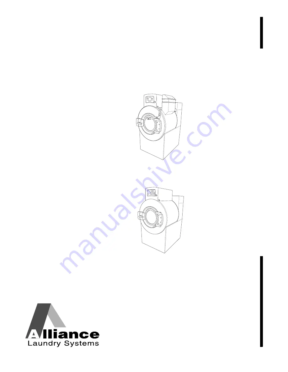
UniLinc and M30 Control

Refer to Page 6 for Model Numbers

PHM848N

PHM847N

UniLinc

45 AND 65 MODELS

M30

45 AND 65 MODELS

PHM847N

PHM848N

Part No. F8410701ENR3

November 2012

Keep These Instructions for Future Reference.

(If this machine changes ownership, this manual must accompany machine.)

Summary of Contents for UWL045K1L

Page 1: ...ount UniLinc and M30 Control Refer to Page 6 for Model Numbers PHM848N PHM847N UniLinc 45 AND 65 MODELS M30 45 AND 65 MODELS PHM847N PHM848N Part No F8410701ENR3 November 2012 Keep These Instructions...

Page 2: ......

Page 3: ...allation on Existing Floor 16 Elevated Pad Installation on Existing Floor 16 New Foundation 16 Isolated Pad Installation 16 Machine Foundation and Pad Installation 17 Machine Installation L speed and...

Page 4: ...01 EN Copyright Alliance Laundry Systems LLC DO NOT COPY or TRANSMIT Maintenance 46 Daily 47 Beginning of Day 47 End of Day 47 Weekly 47 Monthly 48 Quarterly 49 Care of Stainless Steel 50 Disposal of...

Page 5: ...mbustible products Do not add the following substances or textiles containing traces of the following substances to the wash water gasoline kerosene waxes cooking oils vegetable oils machine oils dry...

Page 6: ...r lid while the machine is running 16 Do not attach anything to the supply dispenser s nozzles if applicable The air gap must be maintained 17 Do not operate the machine without the water reuse plug o...

Page 7: ...connect power and call a service technician 3 Do not attempt to operate the machine if any of the following conditions are present a The door does not remain securely locked during the entire cycle b...

Page 8: ...5K1M UWN045T3V UWU045K2M UWL045K2L UWN045T4V UWU045T3V UWL045K2M UWN065K1L UWU045T4V UWL045T3V UWN065K1M UWU065K1L UWL045T4V UWN065K2L UWU065K1M UWL065K1L UWN065K2M UWU065K2L UWL065K1M UWN065T3L UWU06...

Page 9: ...sistance Nameplate Information UniLinc Models On UniLinc models nameplate information is also programmed into the control To access machine ID through the control 1 Press and hold then then keypads at...

Page 10: ...at Crate shipping volume ft3 m3 97 0 3 97 0 3 Slat Crate shipping dimensions WxDxH in mm 41 7 x 56 8 x 70 8 1060 x 1440 x 1800 41 7 x 56 88 x 70 8 1060 x 1440 x 1800 Wash Cylinder Information Cylinder...

Page 11: ...ction Out of balance switch installed STD STD Direct Steam Heating Optional Steam inlet connection size in mm 0 5 13 0 5 13 Number of steam inlets 1 1 Steam required to raise bath temperature 10 F lb...

Page 12: ...N Figure 1 PHM867N HH BB FRONT Z N A GG EE B Q EE J L M DD K II FF P 45 65 MODELS R O CC C S T BACK SIDE H G E D F I JJ U V AA W X Y SPRAY RINSE CONNECTION PRIMARY FILL CONNECTIONS 875 CHEM SUPPLY ELE...

Page 13: ...64 mm 10 41 in 2 64 mm O 14 64 in 372 mm 14 64 in 372 mm P 16 12 in 409 mm 16 12 in 409 mm Q 21 93 in 557 mm 21 93 in 557 mm R 28 81 in 732 mm 28 81 in 732 mm S 55 43 in 1408 mm 55 43 in 1408 mm T 55...

Page 14: ...For single machine installations or two machines installed back to back use the outside bolt holes marked A For multiple machines installed side by side with minimum clearance use the inside bolt hol...

Page 15: ...mm D 94 in 24 mm 94 in 24 mm E 4 32 in 110 mm 4 32 in 110 mm F 94 in 24 mm 94 in 24 mm G 1 96 in 50 mm 1 96 in 50 mm H 3 11 in 79 mm 3 11 in 79 mm I 16 in 406 mm 16 in 406 mm J 26 in 660 mm 26 in 660...

Page 16: ...01 EN 14 Floor Layout Figure 3 PHM819N A B MACHINE 1 FRONT MACHINE 2 STANDARD MOUNT SIDE BY SIDE WALL REAR REAR FRONT Floor Layout Specifications Specifications 45 65 A Distance to wall 20 in minimum...

Page 17: ...EN Figure 4 PHM810N A B MACHINE 1 FRONT MACHINE 2 BACK TO BACK REAR FRONT B EDGE OF CONCRETE PAD REAR Floor Layout Specifications Specifications 45 65 A Distance to Back edge of machine 2 20 in minim...

Page 18: ...T desired refer to Figure 5 and proceed to Machine Mounting and Grouting section Elevated Pad Installation on Existing Floor The existing floor slab must be 12 in 305 mm thick reinforced concrete with...

Page 19: ...und portion of the foundation Verify that the top of the foundation is level The height of the foundation pad must not exceed 8 inches 203 mm above the existing floor 4 Backfill with clean fill dirt 5...

Page 20: ...one piece 12 Allow concrete to cure refer to manufacturer s recommended cure times 13 Using a mounting bolt template or machine base mark where the holes should be drilled to mount the machine NOTE As...

Page 21: ...LOOR A 6 in 152 mm PHM852N A Existing Floor D Perimeter Reinforcing Bar B 3500 PSI minimum Concrete E Compacted Fill C Reinforcing Bar Figure 6 PHM873N A Existing Floor D Perimeter Reinforcing Bar B 3...

Page 22: ...8 in 203 mm PHM874N A Existing Floor D Perimeter Reinforcing Bar B 3500 PSI minimum Concrete E Compacted Fill C Reinforcing Bar Figure 9 PHM853N A Existing Floor D Perimeter Reinforcing Bar B 3500 PSI...

Page 23: ...305 mm PHM875N A Existing Floor D Perimeter Reinforcing Bar B 3500 PSI minimum Concrete E Compacted Fill C Reinforcing Bar Figure 12 PHM853N A Existing Floor D Perimeter Reinforcing Bar B 3500 PSI min...

Page 24: ...mmended adhesive cure times 8 Remove shipping materials and place the machine carefully over the bolts Never attempt to lift the machine by the door handle or by pushing on the cover panels Always ins...

Page 25: ...washers and minimum Grade 5 SAE rating serrated hex flange locknuts are the recommended hardware for anchoring machine to bolts 11 Position the flat washers and locknuts on the anchor bolts and finge...

Page 26: ...5 9 Static pressure lb ft2 kN m2 153 7 3 163 7 8 Maximum dynamic load lb kN 2700 12 2700 12 Maximum dynamic pressure lb ft2 kN m2 470 22 5 480 23 0 Dynamic load frequency Hz L Speed 7 95 7 95 M Speed...

Page 27: ...drainage is not possible Increasing the drain hose length installing elbows or causing bends will decrease drain flow rate and increase drain times impairing machine performance Figure 17 Refer to Tab...

Page 28: ...a drain trough As an option the drain pipe can instead be routed straight across or down and be suspended above drain trough by at least 3 inches 76 mm 2 Secure the drain pipe with the hose clamp IMP...

Page 29: ...uld be installed in supply lines to prevent hammering Refer to Figure 19 For machines labeled with the CE mark backsiphon protection devices must be installed previous of all machine water inlet valve...

Page 30: ...n power supply free from voltage spikes and surges Use voltage monitor to check incoming power The following conditions require corrective action contact the local utility to adjust the voltage If the...

Page 31: ...on local code requirements Refer to serial plate for recommended wire sizes for runs up to 50 feet 15 24 meters Use next larger size for runs of 50 to 100 feet 15 24 to 30 48 meters Use 2 sizes larger...

Page 32: ...15 50 60 3 3 6 15 14 2 5 32 40 8 10 0 X 200 240 50 60 1 3 2 3 11 8 15 14 2 5 Not Available Variable Speed Models Q 200 240 50 60 3 3 9 15 14 2 5 71 80 4 25 0 N 440 480 50 60 3 3 6 15 14 2 5 36 40 8 10...

Page 33: ...4 4 0 2 5 Not Available Variable Speed Models Q 200 240 50 60 3 3 10 15 14 2 5 71 80 4 25 0 N 440 480 50 60 3 3 7 15 14 2 5 37 40 8 10 0 P 380 415 50 60 3 3 8 15 14 2 5 33 40 8 10 0 X 200 240 50 60 1...

Page 34: ...0 P 380 415 50 3 3 7 10 2 5 32 40 4 0 X 200 240 50 1 3 2 3 11 8 16 10 2 5 Not Available Variable Speed Models Q 220 240 50 3 3 11 16 2 5 71 80 25 0 N 440 480 60 3 3 6 15 2 5 36 40 10 0 P 380 415 50 3...

Page 35: ...0 2 5 Not Available Variable Speed Models Q 220 240 50 3 3 11 16 2 5 71 80 25 0 N 440 480 60 3 3 7 15 2 5 37 40 10 0 P 380 415 50 3 3 8 10 2 5 33 40 4 0 X 200 240 50 1 3 2 3 17 11 20 16 2 5 Not Availa...

Page 36: ...ial steam practices Steam requirements are shown in Table 13 NOTE Failure to install the supplied steam filter may void the warranty Steam Supply Information 45 65 Steam inlet connection in mm 1 2 DN1...

Page 37: ...s must be drilled through with a 3 16 inch diameter drill bit before connecting chemical lines Refer to Figure 22 Figure 22 Dangerous Chemicals May damage eyes and skin Wear eye and hand protection wh...

Page 38: ...e plastic cup with the exception of the softener tube which should be routed to the outside of the cup 4 Tighten the seal nut to prevent tubing from escaping the assembly 5 Before operating machine co...

Page 39: ...ication wiring Communication wiring connections which include a single row of identified terminal blocks can be found under a service panel at the upper back of the machine Chemical Injection Using In...

Page 40: ...s or less 1 Remove the red jumper wire installed by the factory between 24VAC and RELAY COM 2 Connect one side of the external power to the RELAY COM and the other to the external dispenser input sign...

Page 41: ...the next step signal can be received from the supply equipment For example if ES1 is selected the K1 contact will close and power will be supplied to Supply 1 Signal The contact will remain closed fo...

Page 42: ...Copyright Alliance Laundry Systems LLC DO NOT COPY or TRANSMIT Specifications and Dimensions F8410701 EN 40 PHM824N 1 ES1 Power supply 3 Supply 1 Signal 2 K1 Contact Figure 27 Power Neutral 3 1 2...

Page 43: ...small nets in a load 4 Close the door 5 Add dry supplies to the supply dispenser compartment cups prior to the start of each cycle Liquid supplies can be injected directly into the supply dispenser by...

Page 44: ...The cycle will continue until its completion Then the display will show the door is ready to be opened NOTE Since the machine MUST drain and balance during the drain step before it can extract the con...

Page 45: ...prevent drain blockage IMPORTANT To prevent out of balance conditions premature wear or damage to machine when using laundry nets use several small nets in a load 4 Close the door 5 Add dry supplies i...

Page 46: ...machine MUST drain and balance before it can extract the control will only Rapid Advance to a drain step that occurs before an extract or spray rinse extract step Shakeout Routine A shakeout agitatio...

Page 47: ...alled the safety Out of Balance Switch operation must be verified 1 Locate the green colored switch on the rear left side of the frame 2 Place a large magnet above the normally closed ball switch to v...

Page 48: ...Cycle Menu to enter Service Menu The Service Menu provides a user with a time based service reminder list The list is broken up into DAILY WEEKLY MONTHLY and QUARTERLY The following maintenance proced...

Page 49: ...ter with warm water and allow to air dry Filter can be vacuumed clean IMPORTANT The control module and drive box cover and fan filter must be in place for the fan to properly cool the AC inverter driv...

Page 50: ...ting only 2 strokes 3 Use the following procedures to determine if V belts require replacement or adjustment Call a qualified service technician in either case a Check V belts for uneven wear and fray...

Page 51: ...shell by wiping with a water soaked sponge or cloth 10 Use compressed air to ensure that all electrical components are free of moisture and dust 11 Remove chemical supply components where applicable a...

Page 52: ...rdinary steel wool or steel brushes Remove discoloration or heat tint from overheating by scouring with a powder or by employing special chemical solutions Do not leave sanitizers or sterilizing solut...

Page 53: ...over to the applicable collection point for the recycling of electrical and electronic equipment Ensuring this product is disposed of correctly will help prevent potential negative consequences for t...

Page 54: ......

Page 55: ......

Page 56: ......

Reviews: