background image

Installation

11

801455

© Copyright, Alliance Laundry Systems LLC – DO NOT COPY or TRANSMIT

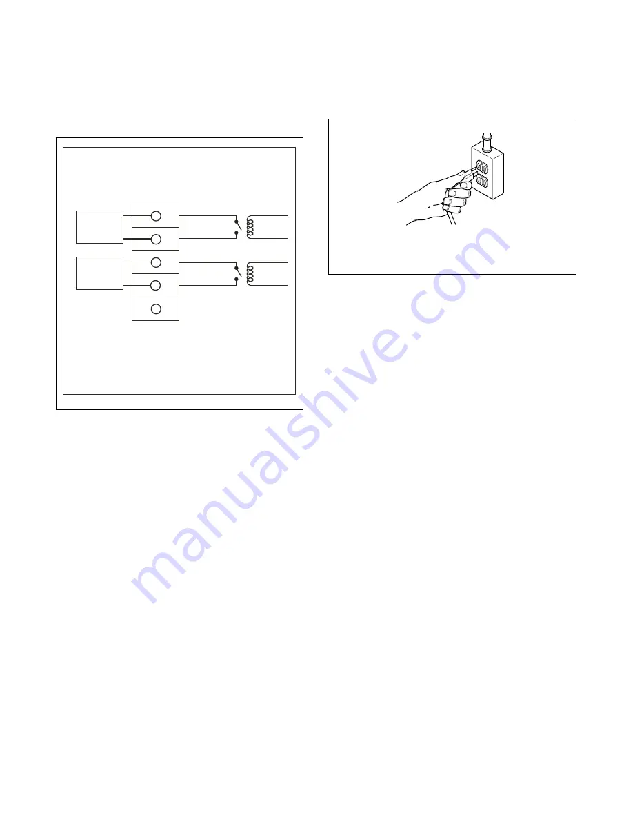
A junction box on the rear panel houses a terminal 

strip which furnishes supply output signals for the 

supply injection pumps.These are dry contacts. 

Voltage needs to be supplied. Refer to 

Figure 14

 for 

the injection interface label. 

These terminals may be used to provide signals to the 

supply injection system but must not be used to 

provide power to the actual pump. 

Any injection system pump which requires 

110 VAC must be powered by a separate external 

power source.

Control Function Test

The washer should be cleaned after the installation is 

complete. A function test should then be executed on 

the unloaded machine:

1. Check the power supply for such characteristics 

as correct voltage, phase, and cycles to be certain 

they are correct for the washer.

2. Open manual shut-off valves to the washer.
3. Apply power to the washer.

Step 8: Plug In the Washer

Refer to section on 

Electrical Requirements

 and connect 

the washer to an electrical power source.

Step 9: Check Installation

Refer to 

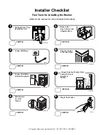
Installer Checklist

 on the back cover and 

make sure that unit is installed correctly.

Moving Unit to a New Location 

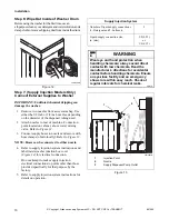
To prevent damage while moving the unit, the 

shipping materials MUST BE reinstalled.

Reinstallation of Shipping Materials

Disconnect washer from electrical supply.
Remove front access panel by removing two screws.
Place the shock sleeves on all four shock absorbers. 

Refer to 

Figure 16

.

Insert hooked end of shipping brace into the open slot 

of the motor mount. Attach with bolts and lockwashers. 

Refer to 

Figure 16

.

Reinstall front access panel.

FLW2028N

Figure 14 

DETERGENT

DISPENSER

CONNECTION

SOFTENER

DISPENSER

CONNECTION

SOFTENER

RELAY

DETERGENT

RELAY

CHEMICAL INJECTION

ELECTRICAL INTERFACE

NO CONNECTION

TERMINAL

BLOCK

YELLOW

YELLOW/BLACK

RED

RED/BLACK

801653R1

NOTE: Normally Open Contacts.
            Contacts Close to Start Chemical Injection.
            Maximum Load Connection per Contact:
            1A @ 120VAC/240VAC 

D254I

Figure 15 

D254I

Plug cord into separately fused 15 Amp circuit.

Summary of Contents for 801455R2

Page 1: ...hers FLW1522C FLW1522C Part No 801455R2 April 2012 Keep These Instructions for Future Reference If this machine changes ownership this manual must accompany machine Para bajar una copia de estas instr...

Page 2: ......

Page 3: ...Washer 5 Step 1 Position Washer Near Installation Area 5 Step 2 Connect Fill Hoses 5 Step 3 Connect Drain Hose to Drain Receptacle 6 Step 4 Position and Level the Washer 8 Step 5 Remove the Shock Sle...

Page 4: ...ement Parts If replacement parts are required contact the source from which you purchased your washer or contact Alliance Laundry Systems Shepard Street P O Box 990 Ripon WI 54971 0990 U S A Phone 920...

Page 5: ...FLW2092N 28 in 71 1 cm 2 in 5 1 cm 17 5 in 44 8 cm 41 2 in 104 6 cm 14 3 in 36 3 cm 29 6 in 75 1 cm 31 1 in 79 cm 26 9 in 68 3 cm MODELS WITH OLD STYLE DOOR FLW2044N FLW2044N 28 in 71 1 cm 2 in 5 1 c...

Page 6: ...0 and 120 pounds per square inch 138 to 827 kPa For more detailed information refer to section on Water Supply Requirements Accessories Bag An accessories bag has been shipped inside your washer It in...

Page 7: ...ection on Water Supply Requirements before connecting fill hoses Turn on the water supply faucets and flush the lines for approximately two minutes to remove any foreign materials that could clog the...

Page 8: ...ng the hose from the retainer clamp and by removing shipping tape Find the instructions on the following pages that are appropriate for your type of drain receptacle standpipe sink wall or laundry tub...

Page 9: ...om dislodging during use Figure 7 In the Wall Installation For installations of this type the drain hose MUST be secured to one of the fill hoses using the beaded tie down strap from accessories bag N...

Page 10: ...op panel Refer to Figure 10 Tighten the locknuts securely against the washer base using the 7 8 in wrench If the locknuts are not tight washer will move out of position during operation NOTE DO NOT sl...

Page 11: ...ransport unit from front or without shipping materials installed Store the shipping materials in the bag provided in the accessories bag Save materials for use whenever the unit is moved NOTE The ship...

Page 12: ...e 13 NOTE Hoses can be connected to either nozzle 4 Refer to supply injection system instructions and label inside washer junction box cover Figure 14 for electrical connection Do not attempt to make...

Page 13: ...ug In the Washer Refer to section on Electrical Requirements and connect the washer to an electrical power source Step 9 Check Installation Refer to Installer Checklist on the back cover and make sure...

Page 14: ...into a polarized three slot effectively grounded receptacle rated 110 120 Volts AC alternating current 15 Amps Refer to Figure 18 to determine correct polarity of the wall receptacle H336I 1 Shock Sle...

Page 15: ...E CIRCUIT DO NOT OVERLOAD CIRCUITS Do not operate both a washer and gas dryer on the same circuit Use separately fused 15 Amp circuits To reduce the risk of an electric shock or fire DO NOT use an ext...

Page 16: ...ill Hose 8 ft 2 44 m No 20618 Fill Hose 10 ft 3 05 m Water Pressure Pressure must be a minimum of 20 to a maximum of 120 pounds per square inch 138 to 827 kPa static pressure measured at the faucet NO...

Page 17: ...nce Laundry Systems Shepard Street P O Box 990 Ripon WI 54971 0990 U S A Date Purchased Model Number Serial Number Dealer s Name Dealer s Address Phone Number Service Agency Service Agency Address Pho...

Page 18: ......

Page 19: ......

Page 20: ...PositionWasherNear Installation Area CHECK CHECK CHECK CHECK Position and Level the Washer D254I D254I Remove the Shock Sleeves and Shipping Brace Connect Fill Hoses CHECK W520I H336I CHECK Wipe Out I...

Reviews: