© Copyright, Alliance Laundry Systems LLC – DO NOT COPY or TRANSMIT
506126
18
Gas Dryers
To view the burner flame, remove the lower front
panel of the dryer.
Close the loading door, start the dryer in a heat setting
(refer to the User’s Guide supplied with the dryer); the
dryer will start, the igniter will glow red and the main
burner will ignite.
IMPORTANT: If all air is not purged out of gas
line, gas igniter may go off before gas is ignited. If
this happens, after approximately two minutes
igniter will again attempt gas ignition.
After the dryer has operated for approximately five
minutes, observe burner flame through lower front
panel. Adjust the air shutter to obtain a soft, uniform
blue flame. (A lazy, yellow-tipped flame indicates lack
of air. A harsh, roaring, very blue flame indicates too
much air.) Adjust the air shutter as follows:
1. Loosen the air shutter lockscrew.
2. Turn the air shutter to the left to get a luminous
yellow-tipped flame, then turn it back slowly to
the right to obtain a steady, soft blue flame.
3. After the air shutter is adjusted for proper flame,
tighten the air shutter lockscrew securely.
4. Reinstall the lower front panel.
After the dryer has operated for approximately three
minutes, exhaust air or exhaust pipe should be warm.
For personal safety, lower front panel must
be in place during normal operation.
W046
WARNING
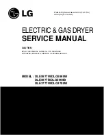
D700I
1
Shut-Off Valve Handle
4
1/8 in. (3.1 mm) Pipe Plug
(For checking manifold pressure)
2
Air Shutter Lockscrew
3
Air Shutter
5
Open Position
6
Closed Position
2
5
3
4
6
1
Summary of Contents for 506126R5
Page 19: ......