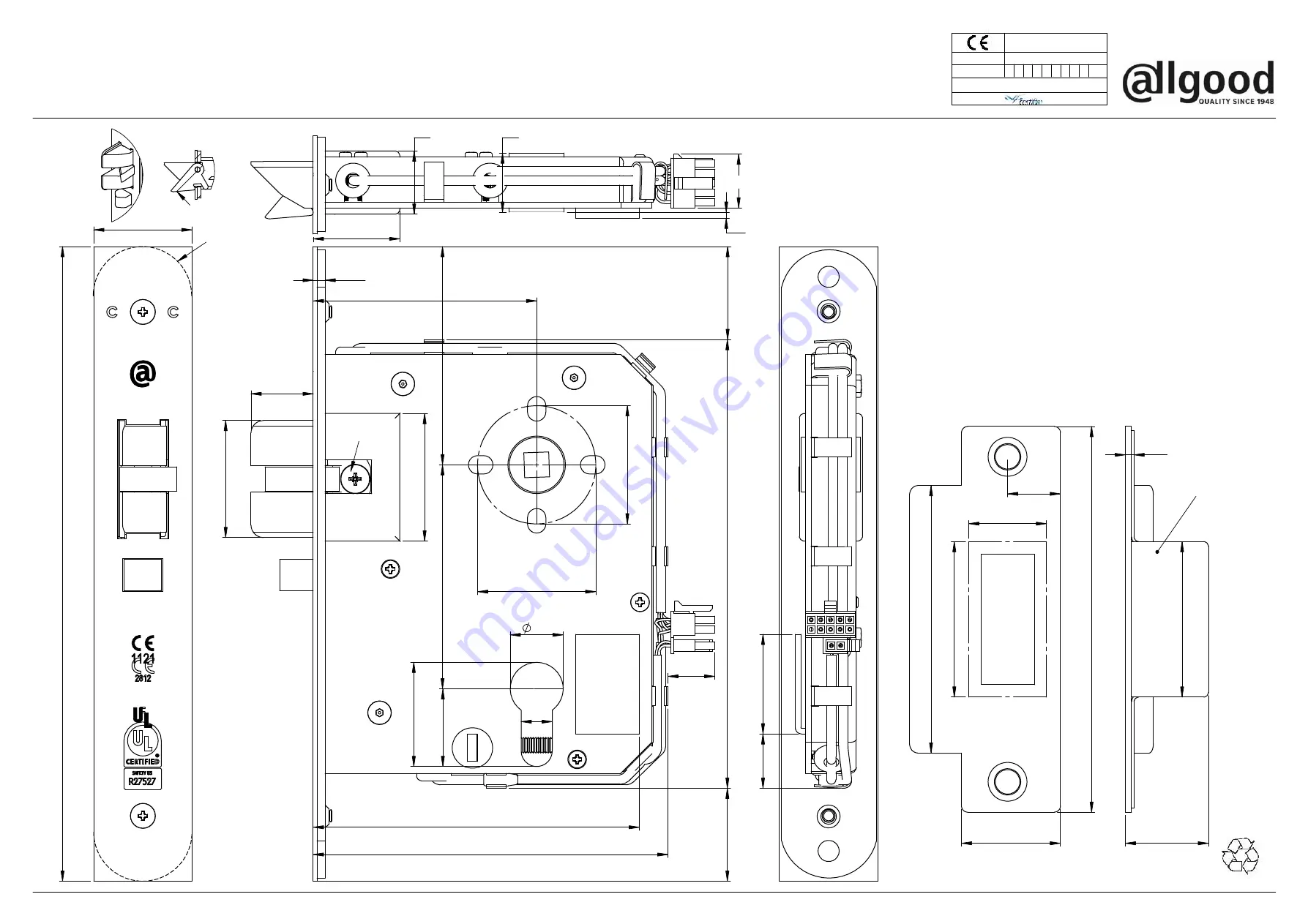
25*
50*
PILOT HOLES ONLY
38 CRS
70
FOR No.6 SCREWS
17
3
8
CRS BB FIX.
MORTAR
GUARD
27
3.0
50
86
124
32
17
204
32
A
38
10
41
20
33.50
4
114
146
16
29
29
72
105
72
25
Wiring diagram
WD9943N
supplied with the lock
19
22
19
2
28
17
33
7
2
2812 ‐ CPR ‐ ABB035
Allgood plc, 63‐83 Brearley Street
refer to actual lockcase to make allowances for cutting tolerances .
(suffix 'F' included to above denotes radiused forend)
1
EN 179:2008
6
Birmingham B19 3NT
* MORTAR GUARD
Reversing the latchbolt
between door and frame
3
3
Issue 01‐08/20
9945N5L&R, 9945N6L&R, 9946N5L&R, 9946N6L&R
Fixing Template for: 9943N5&N6, 9944N5&N6,
•
Some lock functions require certain holes to be cut one side only, check before cutting.
with light oil.
•
When installing this product to an EN 1634
Timber door installation:
metal fire doors upto 240 Min.
Suitable for timber fire doors 30, 60 Min. and
The lock must be supported at the back of the case, the spindle must be
To ensure lock functions correctly and that the warranty conditions are met:
IMPORTANT NOTES:
Dimensions shown are guidance only, and for preperation of door,
MAKE ALLOWANCES FOR WHEN FIRE PACK USED.
FT9943N
B
CF 623
A
4
15
DIMENSIONS
maintain nominal 3mm gap
XX9943NFP for 30 & 60 Min. rating must be used.
B/D
compliant timber fire door, intumescent pack ref:
(see over page for instructions)
Bolts should be checked frequently for easy action, and if required, lubricated
square to the face of door and installed in accordance with the fitting instructions.
•
Important
Before fitting the lock, carefully read the instructions below:
Instructions:
Before cutting the door, check whether lever & cylinder holes are required
1.
on one or both sides of the door.
2. Reversing the latchbolt
a. Remove the retaining screw 'A' from the latchbolt assembly.
b. Pull the latchbolt free.
c. Turn the latchbolt around and twist it back into place in the lockcase,
ensuring that the trigger is hooked behind the forend. (see drg. top left)
d. Replace retaining screw 'A' ensuring it is
fully tightenerd.
3. When using half set of lever, use XX9052NT spindle (supplied C/W Fix. Inst.)
4. Lever rose Assy. must be fitted back to back together using screws provided.
Note:
Screws supplied with Lever Furn. should be fitted through the vertical slots of
the lock case, and additionally No. 6 self tapping screws supplied with lock case fitted
horizontal. (see
Fig. A
overleaf)
Door Gap:
9945N5L&R, 9945N6L&R, 9946N5L&R, 9946N6L&R
(suffix 'F' included to above denotes radiused forend)
T: 020 7387 9951 1 www.allgood.co.uk
Recycle responsibly
Trigger
Recess for
radiused forends


