background image

ESPECIFICACIONES DEL PRODUCTO

ÍNDICE

Información de seguridad .............................................................................................................   

Contenido del paquete ..................................................................................................................  

Aditamentos ..................................................................................................................................

Preparación ................................................................................................................................... 

Instrucciones de ensamblaje ........................................................................................................   

Instrucciones para colgar ..............................................................................................................  

Instrucciones de cableado ............................................................................................................ 

Instalación de la carcasa de la base ............................................................................................. 

Instalación de la bombilla ............................................................................................................. 

Instrucciones de funcionamiento de la cadena del tirador ............................................................


Cuidado y mantenimiento .............................................................................................................

Solución de problemas

 ...........

...................................................................................................... 

Garantía

 ...........

............................................................................................................................. 

Lista de piezas de repuesto

 ...........

............................................................................................... 

20

COMPONENTE

ESPECIFICACIONES

A

B

C

D

E

F

G

H

 I

Ensamble del motor

Bombilla

Control remoto

Unidad receptora

Cubierta para los tornillo de la base

Escudo del techo

Ensamble de la bola para colgar/varilla

Abrazadera para colgar

Cubierta para el acoplador del motor

21

23

24

24

25

27

28

30

31

32

33

33

35

36

Summary of Contents for LP8074LAZ

Page 1: ...P8074LAZ EASTVIEW CEILING FAN ATTACH YOUR RECEIPT HERE Serial Number Purchase Date Questions problems missing parts Before returning to your retailer call our customer service department at 1 888 567 2055 8 a m 5 p m EST Monday Friday ...

Page 2: ...s Canopy Housing Installation Light Bulb Installation Fan Operating Instructions Care and Maintenance Troubleshooting Warranty Replacement Parts List 2 COMPONENT SPECIFICATIONS A B C D E F G H I Motor Assembly Bulb Remote Receiver Unit Canopy Screw Cover Ceiling Canopy Hanger Ball Downrod Assembly Hanger Bracket Motor Coupling Cover 3 5 6 6 7 9 10 12 13 14 15 15 17 18 ...

Page 3: ...fore attempting to assemble operate or install the product If you have any questions regarding the product please call customer service at 1 888 567 2055 8 a m 5 p m EST Monday Friday This device complies with Part 15 of the FCC Rules Operation is subject to the following two conditions 1 This device may not cause harmful interference and 2 this device must accept any interference received includi...

Page 4: ...ect to the two fan lead wires consult an electrician for the proper size wire connectors to use WARNING To reduce the risk of fire electric shock or personal injury do not bend the blade arms when installing them balancing the blades or cleaning the fan Do not insert foreign objects between the rotating fan blades Mount to outlet box marked ACCEPTABLE FOR FAN SUPPORT and use mounting screws provid...

Page 5: ... PART DESCRIPTION QUANTITY A Motor Assembly 1 B Hanger Bracket 1 C Hanger Ball Downrod Assembly D Ceiling Canopy 1 E Canopy Screw Cover 1 F Motor Coupling Cover 1 G Receiver Unit 1 H Remote 1 I Bulb 4 A D H I E F G B C 1 ...

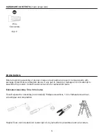
Page 6: ...maged do not attempt to assemble the product Contact customer service for replacement parts Estimated Assembly Time 60 minutes Tools Required for Assembly not included Phillips screwdriver 1 4 in flathead screwdriver wire stripper and step ladder Helpful Tools not included AC tester light do it yourself wiring handbook and wire cutters PREPARATION HARDWARE CONTENTS shown actual size ...

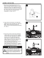
Page 7: ... hanger ball assembly C Fig 2 3 Thread the downrod of the downrod hanger ball assembly C into the downrod support on top of the motor assembly A Install the clevis pin from the downrod hanger ball assembly C by aligning the holes in the downrod support of the motor assembly A with the holes in the downrod of the downrod hanger ball assembly C Secure clevis pin with hairpin clip from the downrod ha...

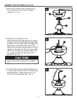
Page 8: ...om the downrod hanger ball assembly C through the two holes in the downrod and align the hanger ball so the pin is captured in the groove in the top of the hanger ball Pull the hanger ball up tight against the pin Securely tighten the set screw in the hanger ball Fig 5 CAUTION A loose set screw could result in a wobbly fan 6 Cut off excess lead wire approximately 6 to 9 in above top of the top of ...

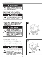
Page 9: ...llboard until bracket contacts box If bracket and or outlet box are not securely attached the fan could wobble or fall B 1 1 Securely attach the hanger bracket B to the outlet box using the outlet box screws and washers supplied with the outlet box not included Fig 1 B C 2 WARNING Failure to seat tab in groove could cause damage to electrical wires and possible shock or fire hazard To avoid possib...

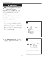
Page 10: ...mitter and receiver WARNING To avoid possible electrical shock be sure electricity is turned off at the main fuse box before hanging 1 To set the transmitter code remove battery cover on remote H by pressing firmly below arrow and sliding cover off Slide code switches to your choice of up or down position Factory setting is all up Do not use this position With a small screwdriver or ball point pen...

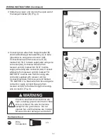
Page 11: ...IN N to white supply wire using wire connector AA Connect white wire from receiver unit G marked TO MOTOR N to white wire from fan using wire connector supplied with receiver unit G Connect black wire from receiver unit marked TO MOTOR L to black wire from fan using wire connector Lastly connect blue wire from receiver unit G to the blue fan light wire using wire connector Fig 4 WARNING Check to s...

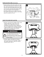
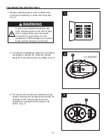
Page 12: ... outlet box Fig 5 WARNING To avoid possible fire or shock make sure that the electrical wires are completely inside the canopy housing and not pinched between the housing and the ceiling 1 Remove one of the two shoulder screws in the hanger bracket B Loosen the second shoulder screw without fully removing it Assemble ceiling canopy D by rotating key slot over shoulder screw in hanger bracket B Tig...

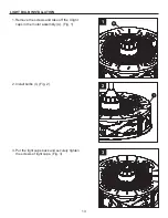
Page 13: ... BULB INSTALLATION 1 Remove the screws and take off the 4 light caps in the motor assembly A Fig 1 1 A I 2 Install bulbs I Fig 2 2 3 Put the light caps back and securely tighten the screws of light caps Fig 3 3 ...

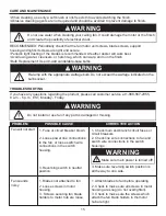
Page 14: ...an off and light on off Varying light levels are available by holding down the light on off button Fig 3 WARNING Check to see that all connections are tight including ground and that no bare wire is visible at the wire connectors except for the ground wire Do not operate fan until the blades are in place Noise and fan damage could result 1 Restore electrical power to the outlet box by turning the ...

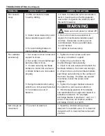
Page 15: ...ill not start 1 Fuse or circuit breaker blown 2 Loose power line connections to the fan or loose switch wire connections in the switch housing 3 Reversing switch in neutral position 1 Check main and branch circuit fuses or circuit breakers 2 Check line wire connections to fan and switch wire connections in the switch housings 3 Make sure reversing switch position is all the way to one side Fan sou...

Page 16: ... and result in a smoother operation For example exchange blades in positions 1 and 3 or 1 and 4 If this does not improve wobble exchange 2 and 4 or 2 and 5 1 If possible consider using a longer downrod For example use a 12 in downrod instead of a 4 5 in downrod that comes with your fan Tighten both set screws and nuts securely in downrod support 2 Tighten the set screw in the downrod hanger ball a...

Page 17: ...tarnishing corroding or peeling Brass finish fans maintain their beauty when protected from varying weather conditions Any glass provided with this fan is not covered by the warranty Any replacement of defective parts for the ceiling fan must be reported within the first year from the date of purchase For the balance of the warranty call our customer service department at 1 888 567 2055 for return...

Page 18: ...P807207LAZ Canopy Screw Cover APPAC1101LAZ Motor Coupling Cover AP1115LAZ Receiver Unit RECAN26 Remote TR350AR Bulb PPE12B40 Wire Connector HDWWNUTS4 A B C D E F G H I PART DESCRIPTION PART AA B C D A I H G E F L AA REPLACEMENT PARTS LIST For replacement parts call our customer service department at 1 888 567 2055 8 a m 5 p m EST Monday Friday ...

Page 19: ... TECHO EASTVIEW Adjuntar su recibo AQUÍ Número de serie Fecha de Compra Preguntas problemas piezas faltantes Antes de volver a la tienda llame a nuestro Departamento de Servicio al Cliente al 1 888 567 2055 8 a m 5 pm hora del Este de lunes viernes ...

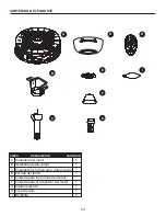
Page 20: ...lla Instrucciones de funcionamiento de la cadena del tirador Cuidado y mantenimiento Solución de problemas Garantía Lista de piezas de repuesto 20 COMPONENTE ESPECIFICACIONES A B C D E F G H I Ensamble del motor Bombilla Control remoto Unidad receptora Cubierta para los tornillo de la base Escudo del techo Ensamble de la bola para colgar varilla Abrazadera para colgar Cubierta para el acoplador de...

Page 21: ...nductor con conexión a tierra de la alimentación eléctrica el conductor del ventilador identificado para la conexión a tierra del equipo se debe conectar al conductor con conexión a tierra del equipo Lea y comprenda completamente este manual antes de intentar ensamblar usar o instalar el producto Si tiene preguntas relacionadas con el producto llame a nuestro Departamento de Servicio al Cliente al...

Page 22: ...ucir el riesgo de incendios descargas eléctricas o lesiones personales los conectores de cable incluidos con este ventilador están diseñados para soportar sólo un cable interior de calibre 12 y dos cables conductores del ventilador Si el cable interior es de un calibre superior a 12 o hay más de un cable interior para conectar los dos cables conductores del ventilador pregúntele a un electricista ...

Page 23: ...N CANTIDAD Ensamble del motor Bombilla Control remoto Unidad receptora Cubierta para los tornillo de la base Escudo del techo Ensamble de la bola para colgar varilla Abrazadera para colgar Cubierta para el acoplador del motor D E F G H I A B C 1 1 1 1 1 1 1 1 4 ...

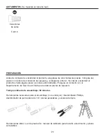
Page 24: ...ucto si falta alguna pieza o si éstas están dañadas Póngase en contacto con el Departamento de Servicio al Cliente para obtener piezas de repuesto Tiempo estimado de ensamblaje 60 minutos Herramientas necesarias para el ensamblaje no se incluyen Destornillador Phillips destornillador de punta plana de 1 4 pinzas pelacables y escalera de tijera Herramientas útiles Luz de prueba CA manual de cablead...

Page 25: ...varilla C Fig 2 3 Haga pasar la varilla del ensamble de la bola para colgar varilla C por el soporte para varilla en la parte superior del ensamble de motor A Instale el pasador de horquilla del ensamble de la bola para colgar varilla C alineando los orificios del ensamble de soporte de la varilla A con los orificios del ensamble de la bola para colgar varilla C Fije el pasador de horquilla con el...

Page 26: ...C a través de los dos orificios de la varilla y alinee la bola para colgar de manera tal que el pasador quede inserto en la ranura de la parte superior de la bola para colgar Sujete la bola para colgar firmemente al pasador Fije bien el tornillo de fijación a la bola para colgar Fig 5 Un tornillo de fijación flojo podría hacer que el ventilador se tambalee PRECAUCIÓN 1 5 2 4 c m a 2 2 8 6 c m 6 Co...

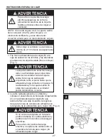
Page 27: ...tar bien asegu rada La abrazadera para colgar debe estar bien asentada contra la caja de salida Si la caja de salida está empotrada retire el panel hasta que la abrazadera haga contacto con la caja Si la abrazadera y o la caja de salida no están bien aseguradas el ventilador podría tambalearse o caerse ADVERTENCIA 2 Levante cuidadosamente el ventilador y coloque el ensamble de la bola para colgar ...

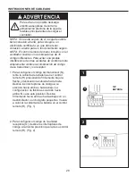
Page 28: ... la unidad receptora G deslice los interruptores de código a la misma posición que la de su control remoto H Fig 2 2 INSTRUCCIONES DE CABLEADO NOTA El control remoto de mano incluido con el ventilador cuenta con combinaciones de 16 códigos diferentes Para evitar una posible interferencia de otras unidades de control remoto simplemente cambie la combinación de código de su transmisor y su receptor ...

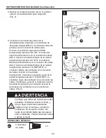
Page 29: ...nte conecte el conductor azul de la unidad receptora G al conductor azul de la iluminación del ventilador con el conector de cables Fig 4 3 Deslice la unidad receptora G en el extremo abierto de la abrazadera para colgar B Fig 3 INSTRUCCIONES DE CABLEADO Continuación Verifique que todas las conexiones estén ajustadas incluida la conexión a tierra y que no haya conductores desnudos visibles en los ...

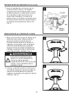
Page 30: ... otro Fig 5 INSTALACIÓN DE LA CARCASA DE LA BASE 1 Retire uno de los dos tornillos de reborde de la abrazadera para colgar Afloje el segundo tornillo de reborde sin retirarlo del todo Ensamble la base de techo D girando el chavetero de la base E sobre el tornillo de reborde de la abrazadera para colgar B Apriete el tornillo de reborde Ensamble por completo el segundo tornillo de reborde que antes ...

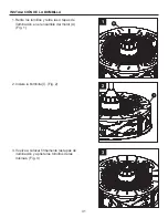
Page 31: ... 1 Retire los tornillos y retire las 4 tapas de iluminación en el ensamble del motor A Fig 1 1 A I 2 Instale la bombilla I Fig 2 2 3 Vuelva a colocar firmemente las tapas de iluminación y apriete los tornillos de las mismas Fig 3 3 ...

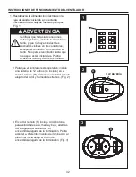
Page 32: ...nación al presionar hacia abajo el botón de encendido apagado de la iluminación Fig 3 1 ON ON ON ON ON ON ON ON INSTRUCCIONES DE FUNCIONAMIENTO DEL VENTILADOR 1 Restablezca la alimentación eléctrica en la caja de salida volviendo a conectar la electricidad de la caja de fusibles principal Fig 1 Verifique que todas las conexiones estén ajustadas incluida la conexión a tierra y que no haya conductor...

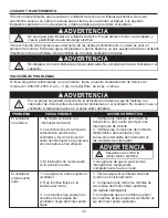
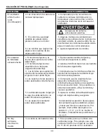
Page 33: ...ite mucho ruido 1 Las aspas no están sujetas al ventilador 2 Hay tornillos flojos en la carcasa del motor 1 Fije las aspas al ventilador antes de ponerlo en funcionamiento 1 Se fundió un fusible o el interruptor de circuito 2 Las conexiones de la línea de alimentación eléctrica del ventilador o las conexiones del cable del interruptor en la carcasa del interruptor se han aflojado 3 El interruptor ...

Page 34: ...e del motor están flojos 1 Fije bien ambos tornillos de fijación y sus tuercas al soporte de la varilla 2 Apriete el tornillo de fijación en el ensamble de la bola para colgar varilla 3 Compruebe que los tornillos que fijan los soportes de las aspas del ventilador al eje del motor estén ajustados 4 Los soportes de las aspas no están asentados correctamente 5 La abrazadera para colgar y o la caja d...

Page 35: ...ón o descascaramiento Los ventiladores con acabado de latón mantienen su belleza cuando se les protege de las cambiantes condiciones atmosféricas La garantía no cubre los elementos de vidrio incluidos con este ventilador El reemplazo de piezas defectuosas para el ventilador de techo debe informarse dentro del primer año a partir de la fecha de compra Para conocer el saldo de la garantía llame a nu...

Page 36: ...do del techo P807207LAZ Cubierta para los tornillo de la base APPAC1101LAZ Cubierta para el acoplador del motor AP1115LAZ Unidad receptora RECAN26 Control remoto TR350AR Bombilla PPE12B40 Conectores de cable HDWWNUTS4 A B C D E F G H I AA PIEZA DESCRIPCIÓN PIEZA Para obtener piezas de repuesto llame a nuestro Departamento de Servicio al Cliente al al 1 888 567 2055 8 a m 5 pm hora del Este de lune...

Reviews: